65
_____________________________________________________________________________________________
4.5 PASS or FAIL Determination
______________________________________________________________________________________________
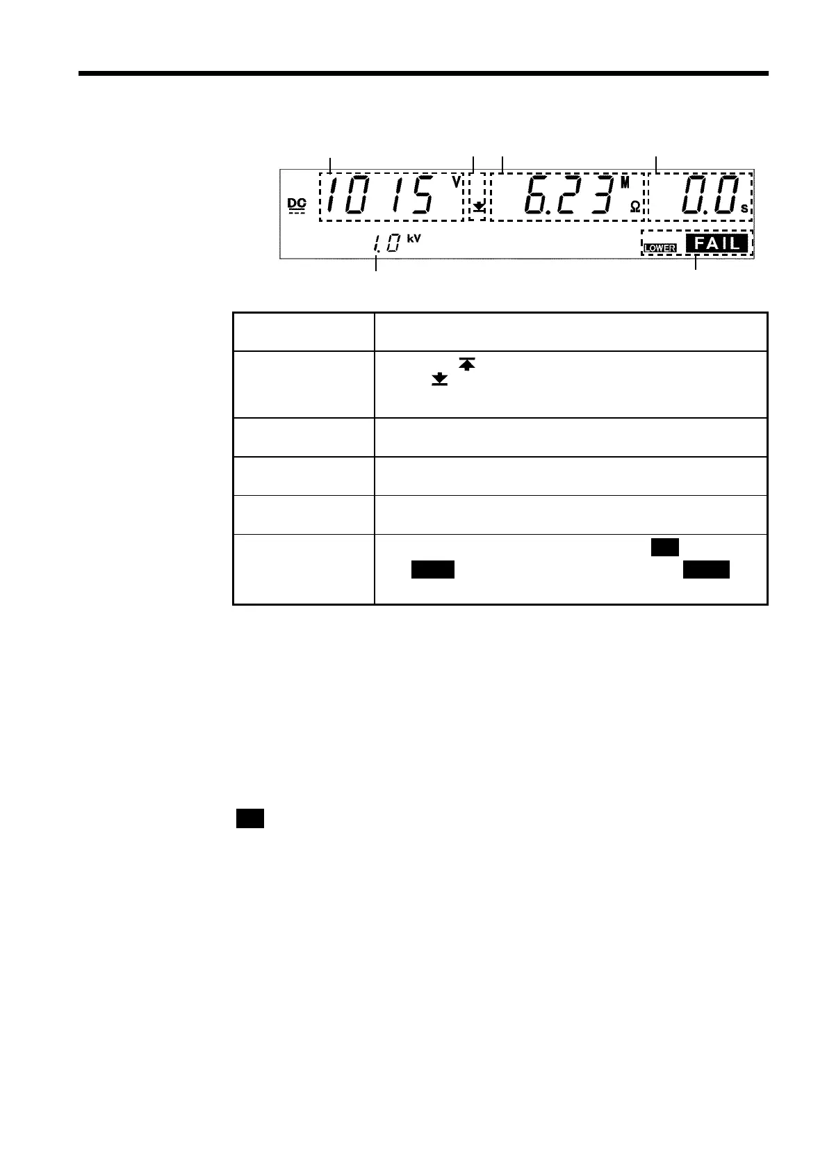
4.5.4 Screening in "FAIL" State
1 2 3
4
5
6
1 Measured
voltage value
Indicates the voltage in the FAIL state.
2 Upper limit value
icon
Lower limit value
icon
The symbol appears when the upper limit value is set,
and the
symbol appears when the lower limit value is
set.
3 Measured
resistance value
Indicates the measured resistance value in the FAIL state.
4 Test completion
time
"
0.0s
" is displayed.
5 Test voltage
range
Indicates the test-voltage value.
6 FAIL
Indicates that the unit is in the FAIL state.
FAIL
lights up
with
UPPER
to indicate UPPER FAIL, and with
LOWER
to
indicate LOWER FAIL.
Danger lamp
Indicates that a voltage is being output. This lamp remains lit as long as a
voltage is being applied to the output terminal.
Analog voltmeter
Does not move in insulation resistance mode.
External I/O
The
I-FAIL
――――――――――
signal and either the
U-FAIL
――――――――――
or
L-FAIL
――――――――――
signal come on when
FAIL
lights on the fluorescent indicator.
Both the
I-FAIL
――――――――――
and
U-FAIL
――――――――――
signals, as well as the
L-FAIL
――――――――――
signal remain
ON as long as the FAIL state is held. The
I-FAIL
――――――――――
,
U-FAIL
――――――――――
and
L-FAIL
――――――――――
signals are turned OFF when the FAIL light on the fluorescent indicator goes
out.
If voltage remains in the output-voltage terminal following the termination of
a test, the
H.V.ON
――――――――――
signal remains ON. When the DANGER lamp goes out,
the
H.V.ON
――――――――――
signal is immediately turned OFF.