75
_____________________________________________________________________________________________
5.4 Starting a Test
______________________________________________________________________________________________
5.4.2 Screening in "TEST State"
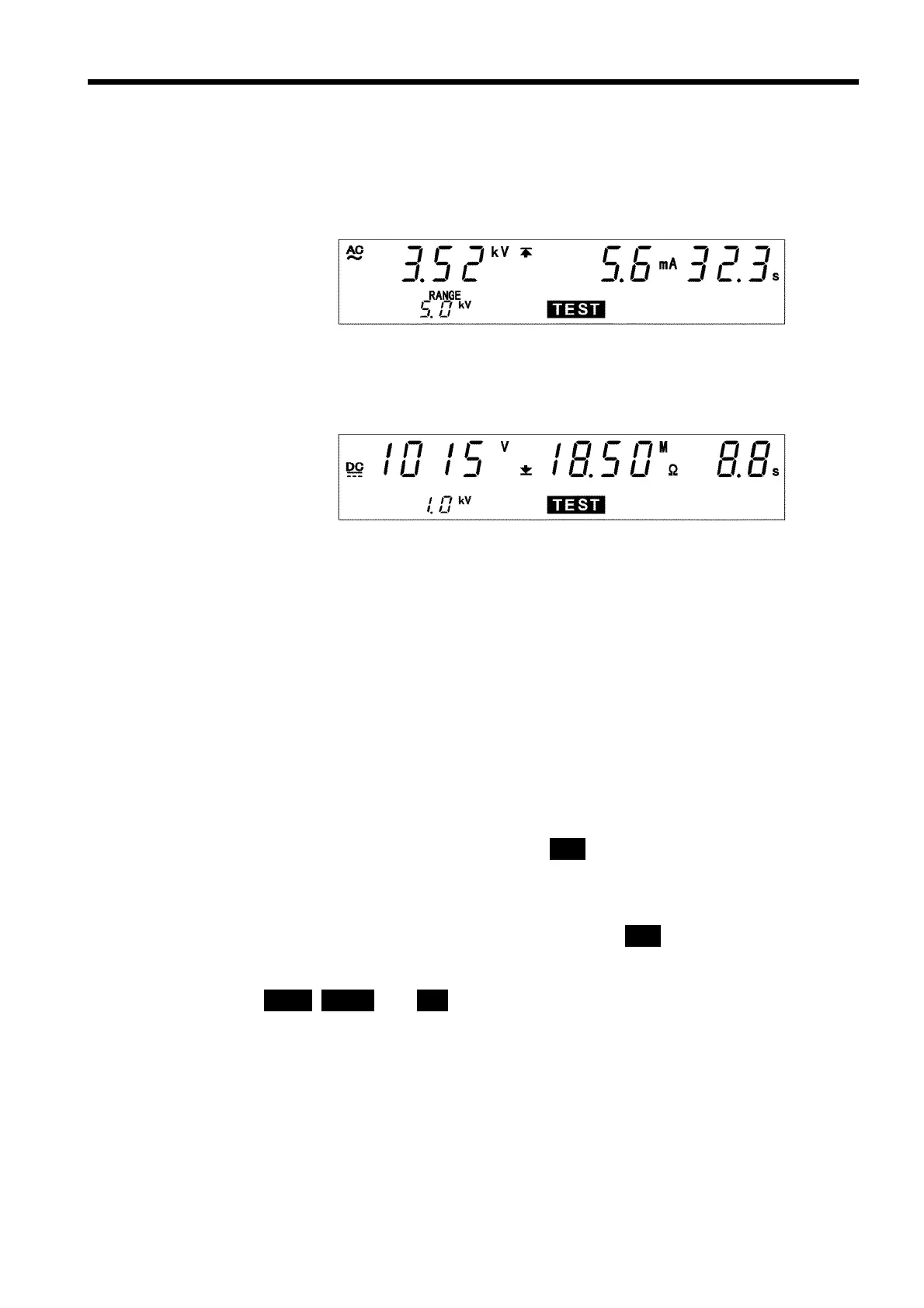
(1) When performing a withstand voltage test:
Similar to the withstand voltage mode TEST state. (See Section 3.4.3)
(2) When performing an insulation resistance test:
Similar to the insulation resistance mode TEST state. (See Section 4.4.2)
Danger lamp
Indicates that a voltage is being output. This lamp remains lit as long as a
voltage of at least 0.03 kV is being applied to the output terminal in the
withstand voltage test.
This lamp remains lit as long as a voltage of at least 50 V is being applied
to the output terminal in the insulation resistance test.
Analog voltmeter
Indicates the voltage being output in withstand voltage test. The analog
voltmeter is not held even if the PASS Hold function is disabled. Does not
move in insulation resistance test.
External I/O
The
TEST
―――――――
signal is turned ON when
TEST
on the fluorescent indicator lights
up. The
H.V.ON
――――――――――
signal is turned on when the DANGER lamp lights up. The
two signals are turned OFF at the same time. At the start of a test, the unit
waits for up to five seconds for the output voltage to switch to the
comparative-voltage range. During this period,
TEST
flickers but the
TEST
―――――――
signal is ON. The
U-FAIL
――――――――――
and
L-FAIL
――――――――――
signals are turned ON when the
output-voltage value deviates from the comparative-voltage value range when
UPPER
,
LOWER
,and
FAIL
are lit.