113
_____________________________________________________________________________________________
8.1 External I/O Terminal
______________________________________________________________________________________________
1
2
3
4
5
6
7
8
9
1
11
1
1
1
1
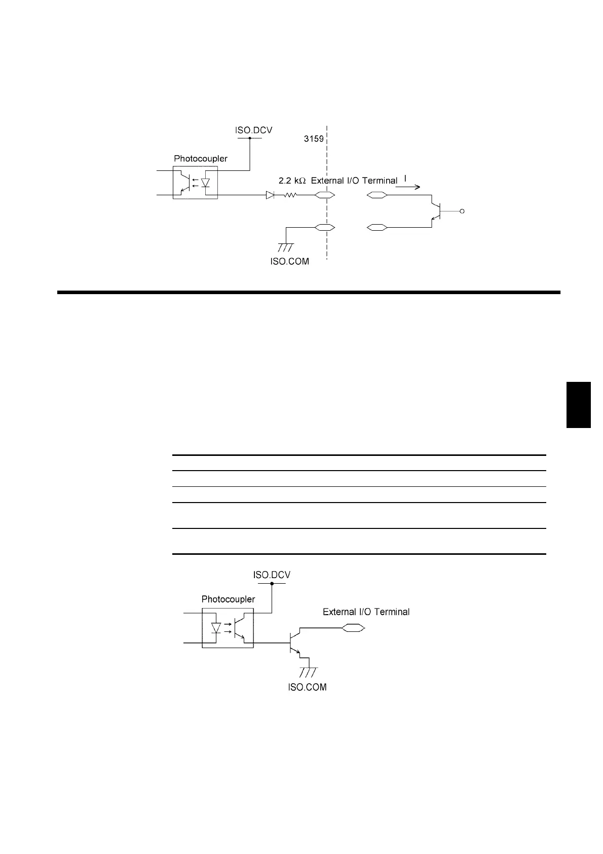
8.1.3 Example of Output Signal Connection
Output signal Open collector output
Max. load 30 VDC
Max. output current 100 mADC per signal
Output saturation
voltage
1.5 VDC or less
Output signals H.V.ON, TEST, PASS, U-FAIL, L-FAIL, READY, W-
MODE, I-MODE, W-FAIL, I-FAIL
(2) Control using the transistor (example)
For control using a transistor or FET, make connections as shown below.
Design the signals so that 6 mA is absorbed into each of the signals.
The output signal becomes Lo depending on the condition of the unit.
Prepare a connector that conforms to the External I/O Specifications. To
enable the external I/O-signal function, set the EXT-E signal (Pin 7) to LOW
level. Connect the EXT-E signal to ISO.COM for the GND signal (Pins 15
to 18). An output example is presented in Section 8.1.5.
EXT I/O Output signals Specifications