36
_____________________________________________________________________________________________
3.4 Starting a Test
______________________________________________________________________________________________
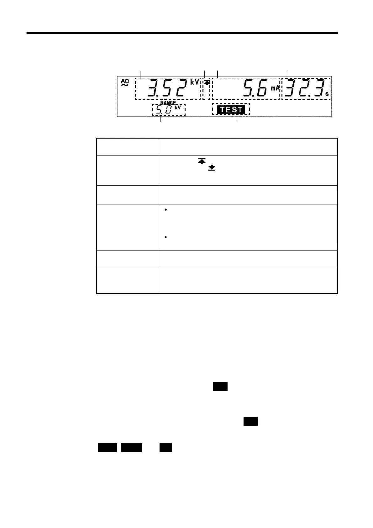
3.4.3 Screening in "TEST" State
1 2 3
4
5
6
1 Measured
voltage value
Indicates the voltage value being output.
2 Upper limit value
icon
Lower limit value
icon
The symbol appears when the upper limit value is set,
and the symbol
appears when the lower limit value is
set.
3 Measured
current value
Represent the value of a current flowing between the HIGH
and LOW terminals.
4 Test time
elapsed
When the testing time is set, countdown starts from the
time set, and is displayed. When the testing time is set to
OFF, the time elapsed after the start of the test is
displayed.
If the elapsed test time exceeds 999 s, "---" is displayed,
but the voltage continues to be output.
5 Output voltage
range
Indicates the output-voltage range.
6 TEST
TEST flickers for up to five seconds at the start of a test
and when the output voltage exceeds the comparativevoltage
range.
Danger lamp
Indicates that a voltage is being output. This lamp remains lit as long as a
voltage of at least 0.03 kV is being applied to the output terminal in the
withstand voltage mode.
Analog voltmeter
Indicates the voltage value being output.
External I/O
The
TEST
--------------------
signal is turned ON when
TEST
on the fluorescent indicator lights
up. The
H.V.ON
----------------------------
signal is turned on when the DANGER lamp lights up. The
two signals are turned OFF at the same time. At the start of a test, the unit
waits for up to five seconds for the output voltage to switch to the
comparative-voltage range. During this period,
TEST
flickers but the
TEST
--------------------
signal is ON. The
U-FAIL
-----------------------------
and
L-FAIL
------------------------
signals are turned ON when the
output-voltage value deviates from the comparative-voltage value range when
UPPER
,
LOWER
,and
FAIL
are lit.