3
_____________________________________________________________________________________________
1.2 Names and Functions of Parts
______________________________________________________________________________________________
1
2
3
4
5
6
7
8
9
1
11
1
1
1
A
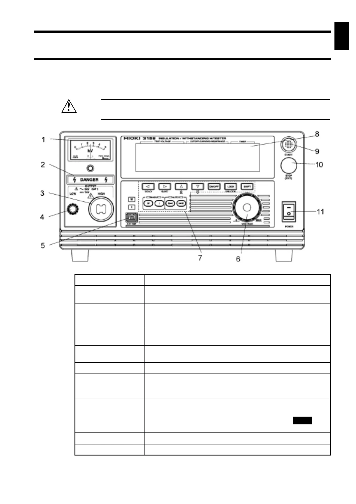
1.2.1 Front panel
WARNING
To prevent electric shock, when the
DANGER
lamp is lit, never touch the
HIGH or LOW terminals, H.V. TEST LEAD, or the tested object.
1 Analog voltmeter
Indicates output-voltage when testing withstand voltage.
2
DANGER
lamp
This lamp lights to warn that voltage is present between the
terminals during testing.
3 HIGH terminal
The HIGH terminal is a high-voltage terminal for voltage outputs.
A high voltage is generated between this terminal and the LOW
terminal.Whenthe
DANGER
lamp is lit, never touch this terminal.
4 LOW terminal
The LOW terminal is a low-voltage terminal for voltage outputs.
It has the same electric potential as the unit body.
5 External switch
terminal
Used for the signal line for the REMOTE CONTROL BOX.
6 Output voltage knob
Sets the output-voltage.
7 Rubber keys
The 10 rubber keys include six function keys and a
SHIFT
key.
The six function keys offer a variety of settings, used in
combination with the
SHIFT
key.
8 VFD (vacuum
fluorescent display)
Displays various information, such as the test state and test results.
9 START key
Used to start a test. This key functions only when the
READY
lamp
is lit.
10 STOP key
Normally used to terminate a test.
11 Main power switch
Powers the 3159 on or off.
1.2 Names and Functions of Parts