81
_____________________________________________________________________________________________
5.5 PASS or FAIL Determination
______________________________________________________________________________________________
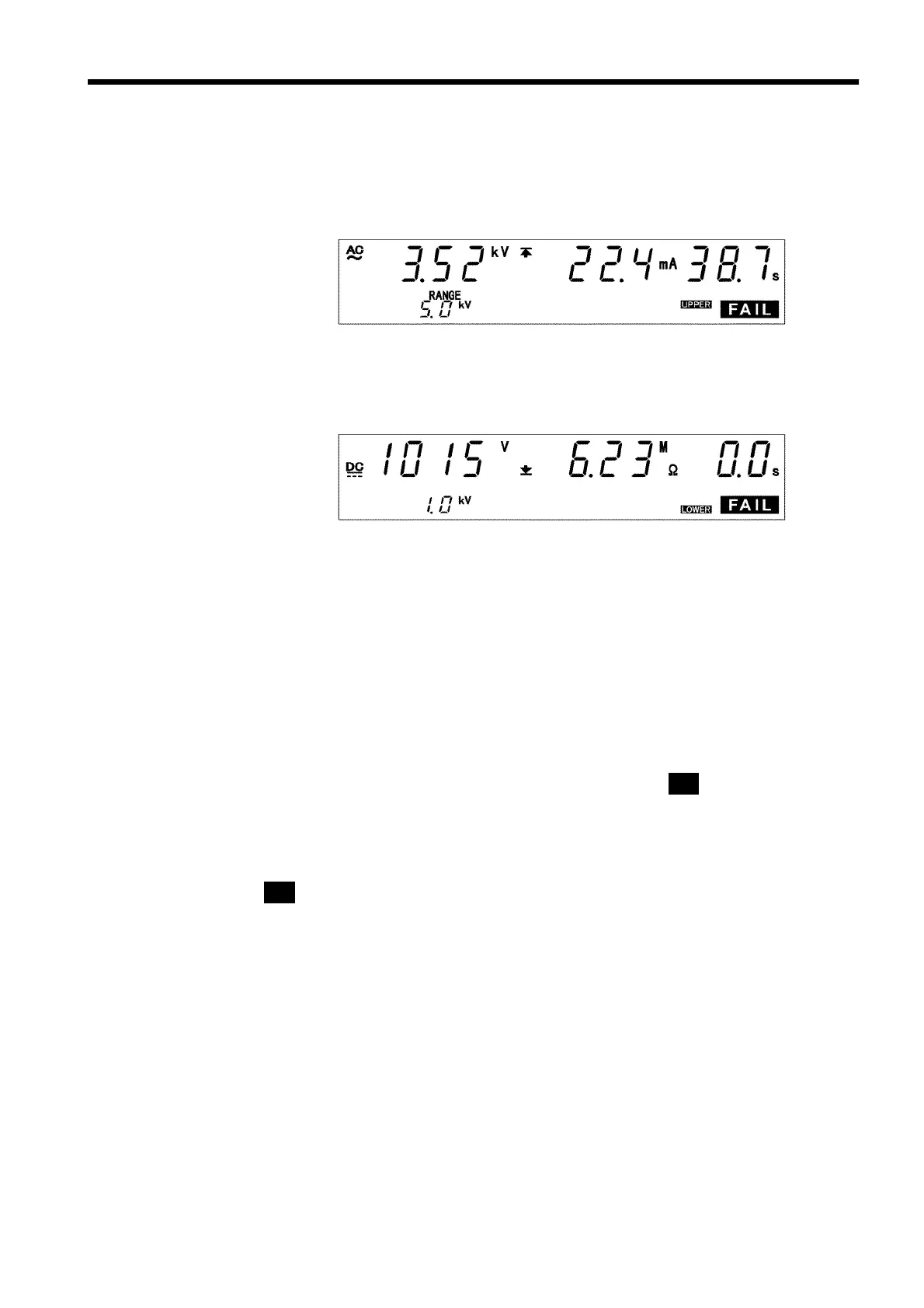
5.5.4 Screening in "FAIL" State
(1) When performing a withstand voltage test:
Similar to the withstand voltage mode TEST state. (See Section 3.5.4)
(2) When performing an insulation resistance test:
Similar to the insulation resistance mode TEST state. (See Section 4.5.4)
Danger lamp
Indicates that a voltage is being output. This lamp remains lit as long as a
voltage is being applied to the output terminal.
Analog voltmeter
Indicates the voltage being output in withstand voltage test. The analog
voltmeter is not held even if the FAIL Hold function is disabled. Does not
move in insulation resistance test.
External I/O
The
W-FAIL
――――――――――
or
I-FAIL
――――――――――
signals are turned on when
FAIL
appears on the
fluorescent indicator, and the
U-FAIL
――――――――――
or
L-FAIL
――――――――――
signals also.
The
W-FAIL
――――――――――
signal or both the
L-FAIL
――――――――――
and
U-FAIL
――――――――――
signals, as well as the
L-FAIL
――――――――――
signal remain ON as long as the FAIL state is held. The
W-FAIL
――――――――――
signal or the
I-FAIL
――――――――――
,
U-FAIL
――――――――――
,and
L-FAIL
――――――――――
signals are turned OFF when
FAIL
goes out on the fluorescent indicator.
If voltage remains in the output-voltage terminal following the termination of
a test, the
H.V.ON
――――――――――
signal remains ON. When the DANGER lamp goes out,
the
H.V.ON
――――――――――
signal is immediately turned OFF.