70
_____________________________________________________________________________________________
5.2 Displaying the READY State
______________________________________________________________________________________________
SHIFT
+
STOP
Displays the Optional functions setting screen.
(See Chapter 6)
START
Test Start (See Section 5.4)
LOCK
Key-lock function (See Section 5.2.1)
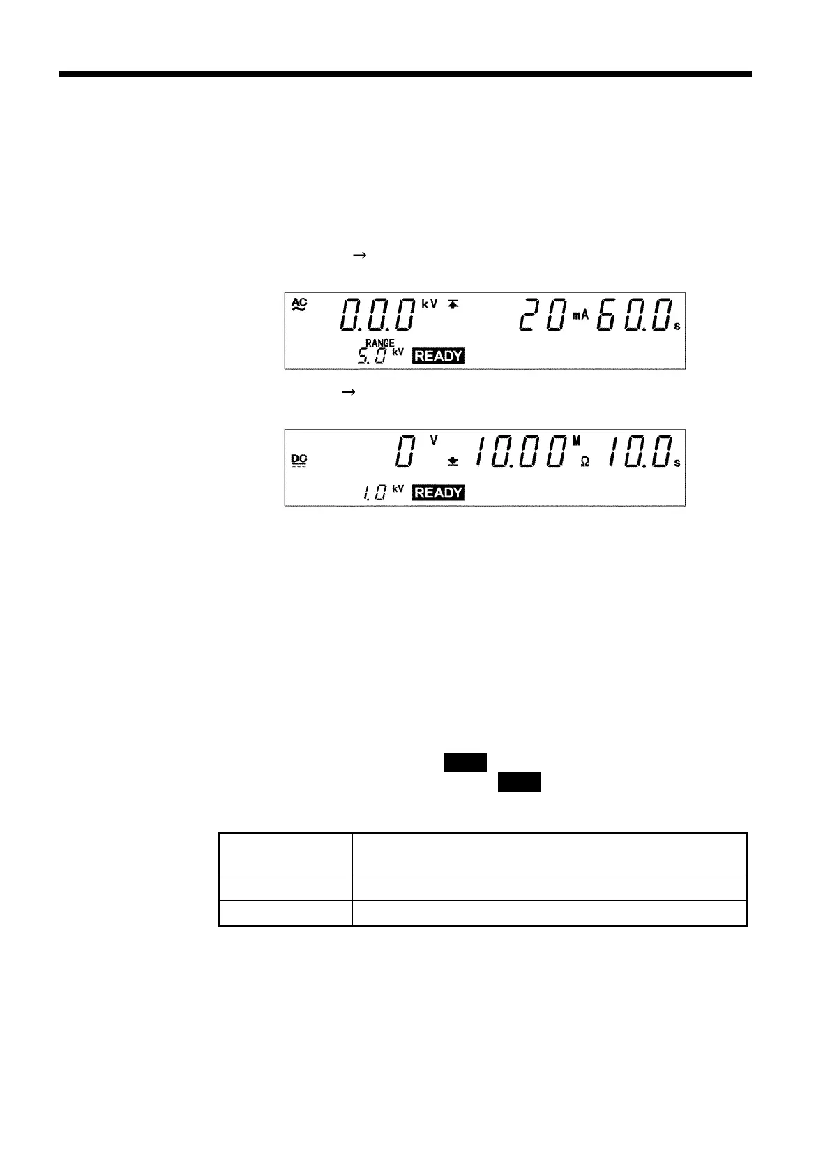
5.2 Displaying the READY State
In the READY state, the unit is always ready to start a test. The unit can be
shifted to the SETTING state only when it is in the READY state. You can
make settings for each test type in a variety of modes.
(See Chapter 3 and Chapter 4)
The settings for W I mode are the same as those for withstand voltage
mode. (See Section 3.2)
The settings for I W mode are the same as those for insulation resistance
mode. (See Section 4.2)
Danger lamp
Indicates that a voltage is being output. This lamp remains lit as long as a
voltage is being applied to the output terminal. It does not light up in the
READY state.
Analog voltmeter
Indicates the voltage value being output in withstand voltage test. In the
READY state, the value remains at 0 kV. Does not move in insulation
resistance mode.
External I/O
The
READY
――――――――――
signal is ON when
READY
is lit on the fluorescent indicator.
The
READY
――――――――――
signal is turned OFF when
READY
is not lit.
Key Operations