5
_____________________________________________________________________________________________
1.2 Names and Functions of Parts
______________________________________________________________________________________________
1
2
3
4
5
6
7
8
9
1
11
1
1
1
A
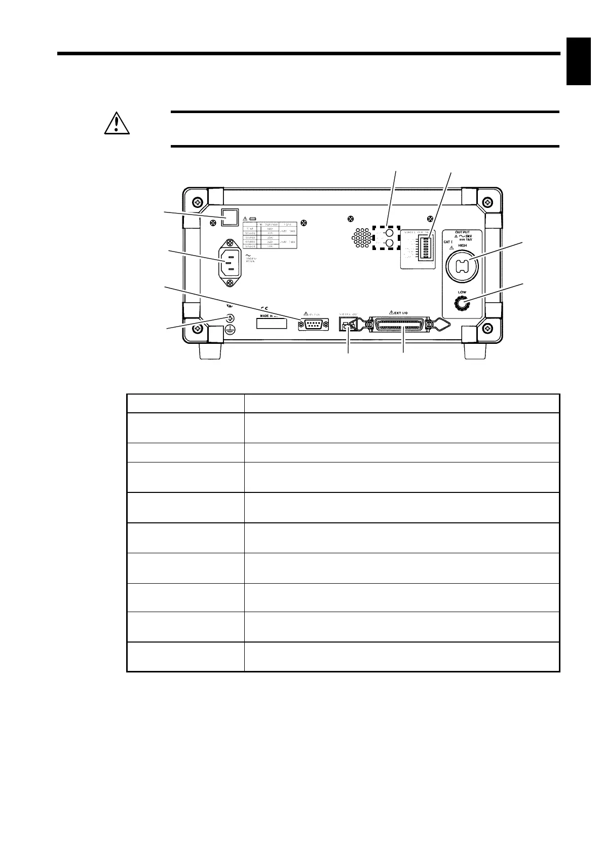
1.2.3 Rear panel
WARNING
To prevent electric shock, when the
DANGER
lamp is lit, never touch the
HIGH or LOW terminals, H.V. TEST LEAD, or the tested object.
1
2
3
4
9
10
5 6
7 8
1 Fuse holder
Contains a power fuse.
2 Power inlet
Connect the grounded three-core power cord supplied here.
Integrated with a fuse holder.
3 RS-232C terminal
Used for remote control with RS-232C.
4 Protective ground
terminal
Used to earth a protective ground wire. Be sure to make grounding
connections before starting a test.
5 Buzzer adjustment
knob
Used for buzzer sound adjustment. Two knobs are provided: one
for PASS screening and one for FAIL screening.
6 STATUS OUT dip
switch
Used to set the output conditions for relay contacts when using the
status out function.
7 STATUS OUT relay
terminal
Switches on the relay contacts if the conditions set with the
STATUS OUT dip switch are met.
8 External I/O
terminal
For output of 3159 state and input of start and stop signals.
9 HIGH terminal
A high-voltage terminal for voltage output. Connected to the HIGH
terminal on the front panel.
10 LOW terminal
A low-voltage terminal for voltage output. Contains the same
electrical potential as this units casing.