44
_____________________________________________________________________________________________
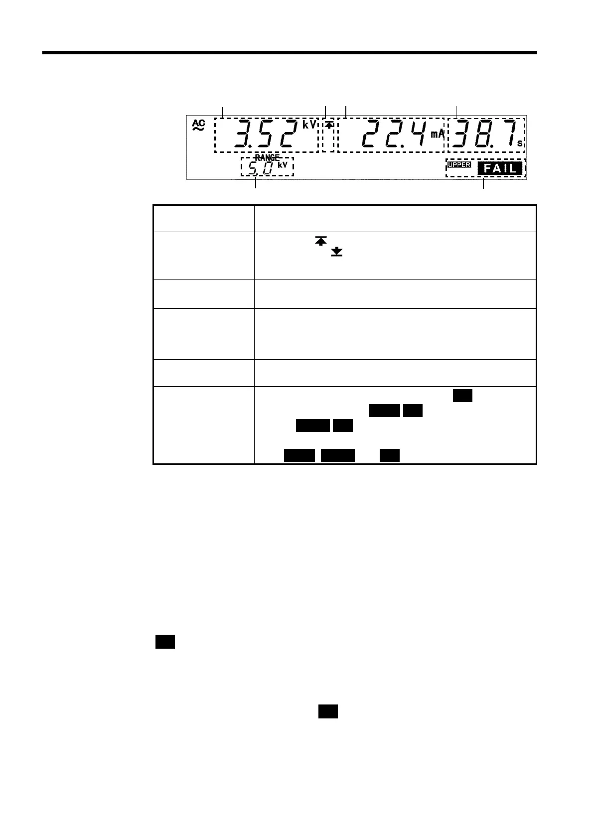
3.5 PASS or FAIL Determination
______________________________________________________________________________________________
3.5.4 Screening in "FAIL" State
1 2 3 4
5
6
1 Measured
voltage value
Indicates the voltage in the FAIL state.
2 Upper limit value
icon
Lower limit value
icon
The symbol appears when the upper limit value is set,
and the symbol
appears when the lower limit value is set.
3 Measured
current value
Indicates the current flowing between the HIGH and LOW
terminals in the FAIL state.
4 Test completion
time
Indicates the time when the unit switched to the FAIL state.
If the test time has been set, the remaining test time is
displayed. If the test time is set at OFF, the period of time
during which a voltage is output is displayed.
5 Output voltage
range
Indicates the output-voltage range.
6 FAIL
Indicates that the unit is in the FAIL state.
FAIL
lights up
with UPPER to indicate
UPPER FAIL
, and with LOWER to
indicate
LOWER FAIL
. If the output voltage deviates from the
comparative-voltage range and switches the unit to the FAIL
state,
UPPER
,
LOWER
,and
FAIL
light up.
Danger lamp
Indicates that a voltage is being output. This lamp remains lit as long as a
voltage of at least 0.03 kV is being applied to the output terminal.
Analog voltmeter
Indicates the voltage being output in withstand voltage test. The analog
voltmeter is not held even if the FAIL Hold function is disabled. Indicates
the voltage value being output.
External I/O
The
W-FAIL
――――――――――
signal and either the
U-FAIL
――――――――――
or
L-FAIL
――――――――――
signal come on when
FAIL
lights on the fluorescent indicator. If the output-voltage deviates from
the comparative-voltage range, both the
W-FAIL
――――――――――
and
U-FAIL
――――――――――
signals, as
well as the
L-FAIL
――――――――――
signal are turned ON.
Both the
W-FAIL
――――――――――
and
U-FAIL
――――――――――
signals, as well as the
L-FAIL
――――――――――
signal remain
ON as long as the FAIL state is held. The
W-FAIL
――――――――――
,
U-FAIL
――――――――――
and
L-FAIL
――――――――――
signals are turned OFF when the
FAIL
light on the fluorescent indicator goes
out. If voltage remains in the output-voltage terminal following the
termination of a test, the
H.V.ON
――――――――――
signal remains ON. When the DANGER
lamp goes out, the
H.V.ON
――――――――――
signal is immediately turned OFF.