112
_____________________________________________________________________________________________
8.1 External I/O Terminal
______________________________________________________________________________________________
8.1.2 Example of Input Signal Connection
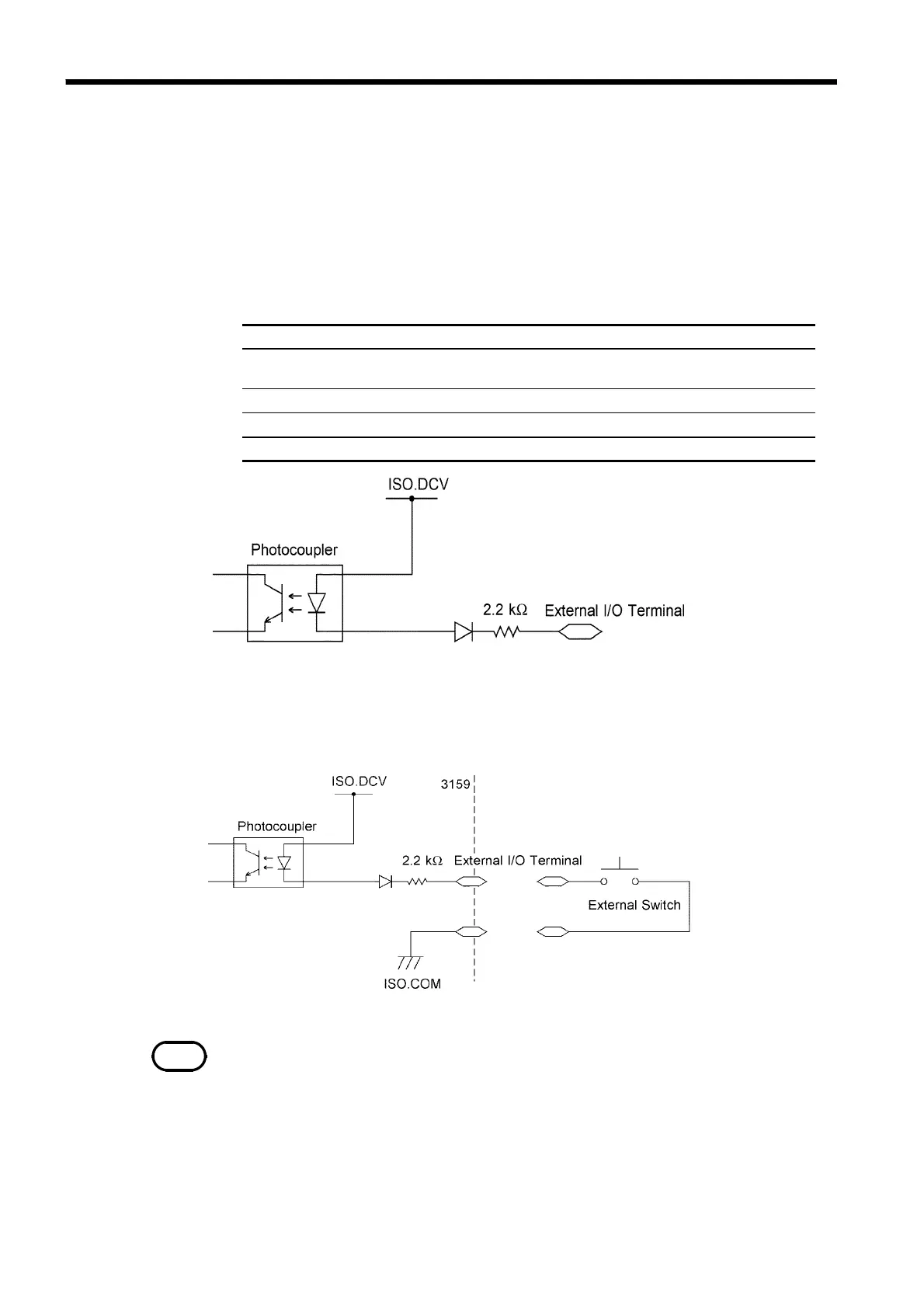
Input signals Active low input ( photocoupler isolated )
Max. testing withstand
voltage
30 VDC
HIGH level voltage 15 VDC or more, open
LOW level voltage 5 VDC or less ( -6 mA typ )
Input signals START, STOP, EXT-E, INTERLOCK
NOTE
For connection to the input signal, provide a circuit that protects the relay and
switch from chattering to prevent malfunctioning.
The unit can be controlled externally using the external I/O input signal.
Provide a connector that conforms to the External I/O Specifications. To
enable the external I/O signal, set the EXT-E signal (Pin 7) to LOW level.
Connect the EXT-E signal to ISO.COM for the GND signal (Pins 15 to 18),
which is insulated from the unit's internal power supply.
EXT I/O Input signals Specifications
(1) Control using the external switch (example)
To control the START and STOP signals using a relay or switch, make
connections as shown below: