111
_____________________________________________________________________________________________
8.1 External I/O Terminal
______________________________________________________________________________________________
1
2
3
4
5
6
7
8
9
1
11
1
1
1
1
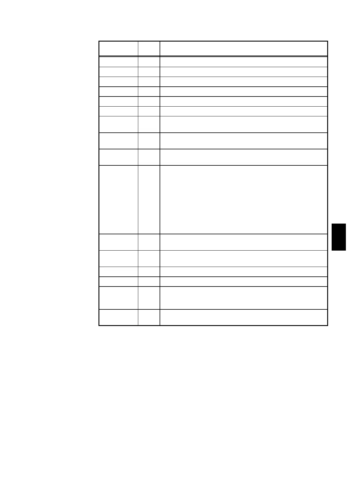
Signal line
name
I/O Function
READY
―――――――
OUT
LOW level in the READY state
L-FAIL
―――――――
OUT
LOW level in the FAIL state at LOWER (minimum value)
U-FAIL
―――――――
OUT
LOW level in the FAIL state at UPPER (maximum value)
PASS
――――――
OUT
LOW level in the PASS state
TEST
――――――
OUT
LOW level in the TEST state
H.V.ON
―――――――
OUT
LOW level when a voltage is generated in the output terminal
EXT-E
―――――――
IN
At LOW level, the external I/O input signal is active.
INT.LOCK
――――――――――――
remains active regardless of this signal.
START
―――――――
IN
LOW level is equivalent to pressing the unit
START
key and
provides the same functions.
STOP
――――――
IN
LOW level is equivalent to pressing the unit
STOP
key and
provides the same functions.
INT.LOCK
―――――――――――
IN
Inter-lock function terminal.
This signal is always active regardless of the status of the
EXT-E
――――――――
terminal.
When connected to ISO.COM, this terminal cancels the
Interlock function, enabling the unit to function properly.
When disconnected, the terminal disables all keys.
To activate the Inter-lock function, set the optional Inter-lock
function to "
1
:Set."
Use this terminal for a protective device against electric
shock that uses an area sensor or the like. See Section 8.1.4.
W-MODE
――――――――――
OUT
LOW level when performing a withstand voltage test in the
Withstand Voltage Test screen.
I-MODE
――――――――
OUT
LOW level when performing an insulation resistance test in
the insulation resistance Test screen.
W-FAIL
――――――――
OUT
LOW level in FAIL state during a withstand voltage test.
I-FAIL
――――――
OUT
LOW level in FAIL state during an insulation resistance test.
ISO.COM IN
Generates an internal GND for the unit.
Used temporarily to activate the external I/O function. Note
that the signal line is not insulated.
ISO.DCV OUT
Outputs a power voltage of 15 V (0.1 A), insulated from the
internal power supply.
(3) Function of the signal line