15
_____________________________________________________________________________________________
2.6 Connecting the REMOTE CONTROL BOX
______________________________________________________________________________________________
WARNING
To prevent electrical shock, turn off the power unit and tested object,
make sure that there is no high voltage being applied to the output,
confirm the following 3 items, and connect the 9615 H.V. TEST LEAD.
(1) The analog voltmeter reads 0 kV.
(2) The
DANGER
lamp is OFF.
(3) The
READY
lamp is lit (it is off in the Double Action mode).
To prevent malfunctions, do not remove the REMOTE CONTROL BOX
following startup. Before removing it, be sure to turn OFF the power.
To avoid electric shock, when using the REMOTE CONTROL BOX,
provide safety measures to keep the output-voltage terminal, tested
object, and H.V. TEST LEAD out of contact with one another when
they are in the TEST state.
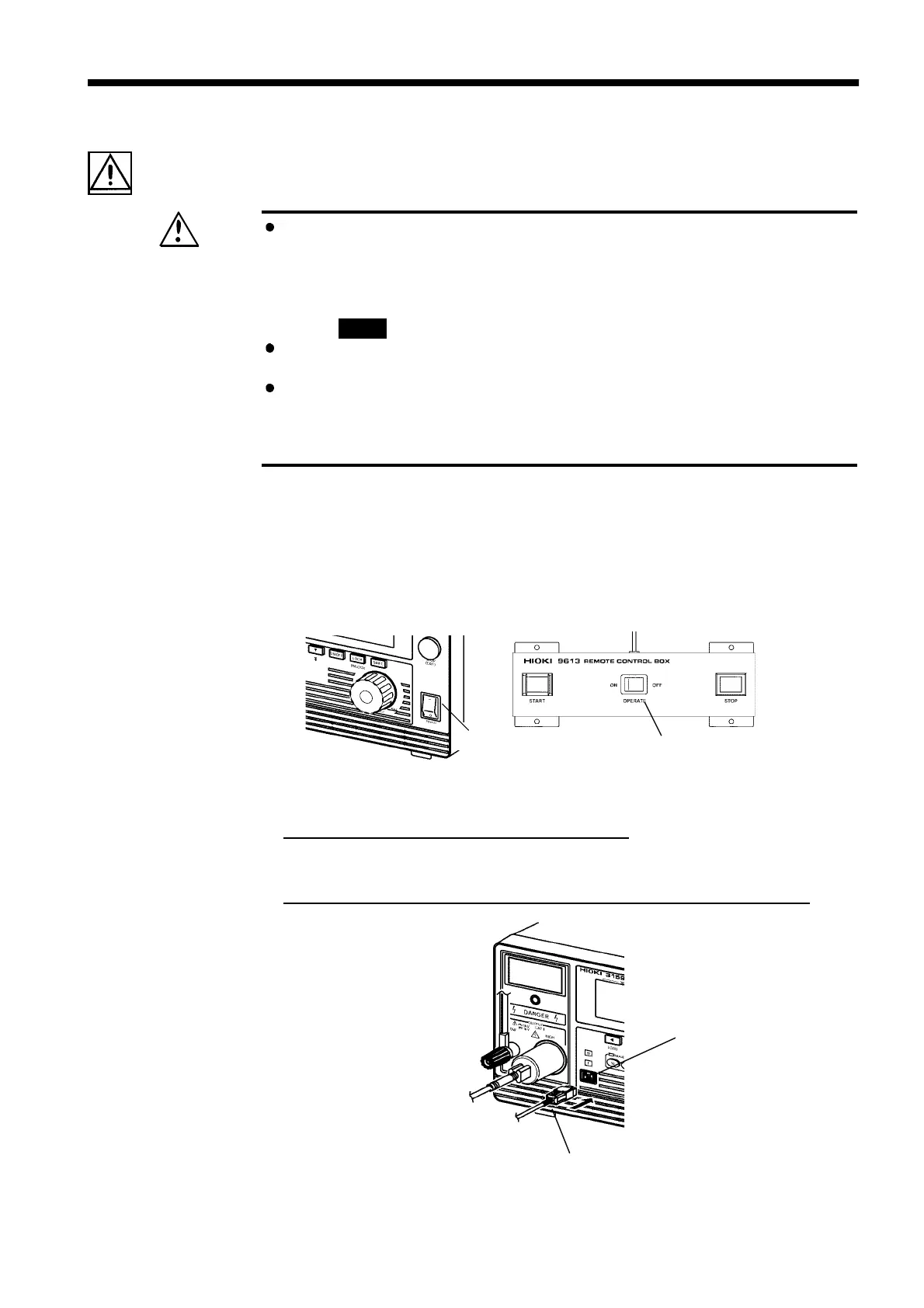
Main power switch
OPERATE
switch on the
REMOTE CONTROL BOX
Switch signal-line plug
External switch terminal
2.6 Connecting the REMOTE CONTROL BOX
Connection of the REMOTE CONTROL BOX (9613/9614) enables start/stop
operations to be performed easily.
1. Make sure the Main Power switch and OPERATE switch on the
REMOTE CONTROL BOX are OFF.
2.
Insert the switch signal-line plug into the external switch terminal.
Check the direction of the switch signal line.
3.
Turn ON the OPERATE switch of the REMOTE CONTROL BOX.
The OPERATE switch can be turned ON/OFF even following startup.