62
_____________________________________________________________________________________________
4.5 PASS or FAIL Determination
______________________________________________________________________________________________
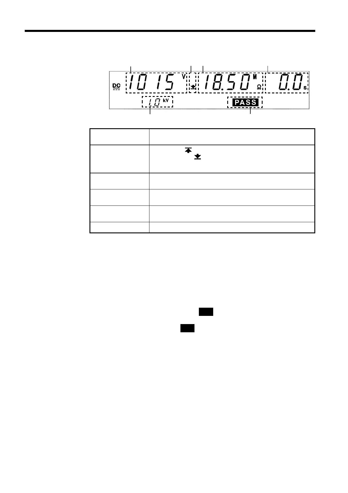
4.5.2 Screening in "PASS" State
1 2 3
4
5
6
1 Measured
voltage value
Indicates the voltage in the PASS state.
2 Upper limit value
icon
Lower limit value
icon
The symbol appears when the upper limit value is set,
and the symbol
appears when the lower limit value is
set.
3 Measured
resistance value
Indicates the measured resistance value in the PASS state.
4 Test time
elapsed
"
0.0s
" is displayed.
5 Test voltage
range
Indicates the test-voltage value.
6 PASS
Indicates that the unit is in the PASS state.
Danger lamp
Indicates that a voltage is being output. This lamp remains lit as long as a
voltage is being applied to the output terminal.
Analog voltmeter
Does not move in insulation resistance mode.
External I/O
The
PASS
―――――――
signal is turned ON when
PASS
on the fluorescent indicator is lit.
As long as the PASS state is held, the
PASS
―――――――
signal remains ON. The
PASS
―――――――
signal is turned OFF when the
PASS
light on the fluorescent indicator goes
out. If voltage remains in the output-voltage terminal following termination
of a test, the
H.V.ON
――――――――――
signal remains ON. When the DANGER lamp goes out,
the
H.V.ON
――――――――――
signal is immediately turned OFF.