117
_____________________________________________________________________________________________
8.1 External I/O Terminal
______________________________________________________________________________________________
8.1.5 Timing Chart of External I/O Terminal
H.V.ON
―――――――
READY
―――――――
TEST
――――――
START
―――――――
Voltage Output
0ms
mini.
100 ms max.
100 ms
max.
160 ms max.
H.V.ON
―――――――
READY
―――――――
TEST
――――――
START
―――――――
Voltage Output
0ms
min.
100 ms
max.
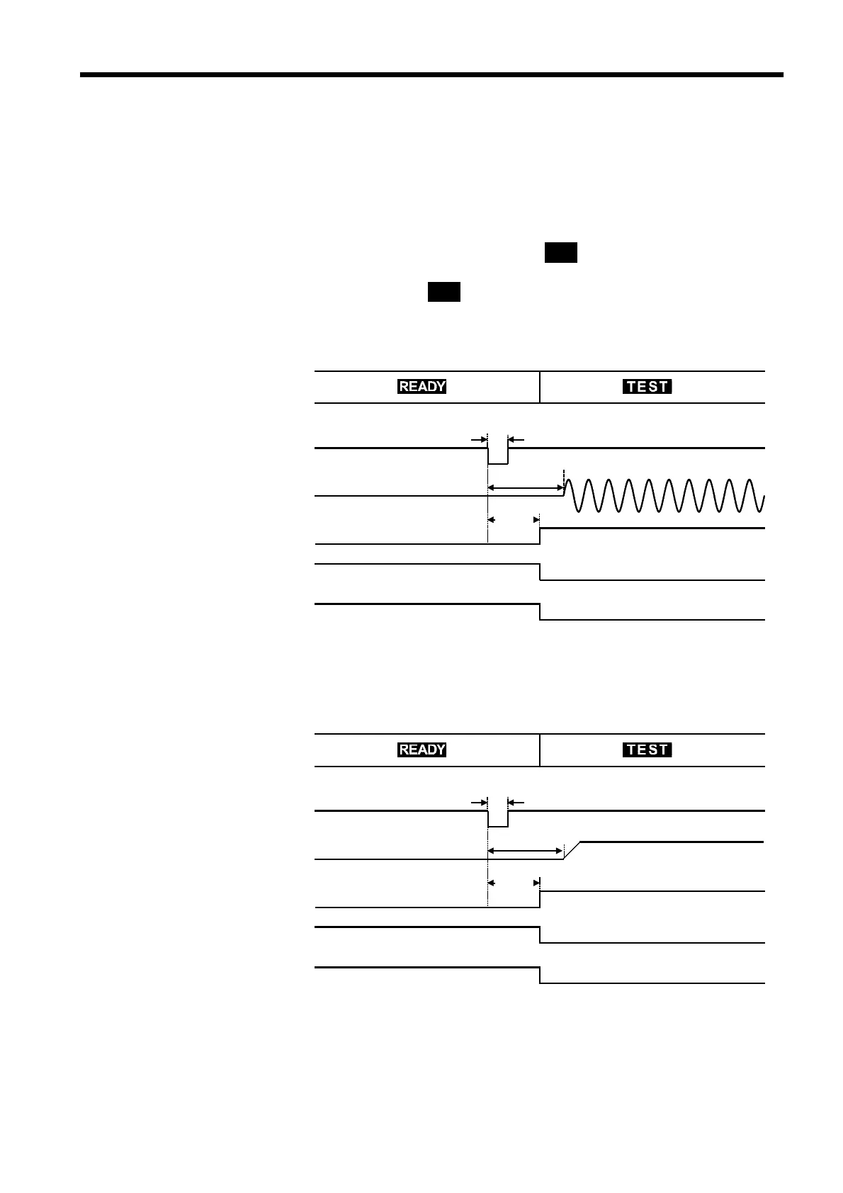
(1) Timing chart at time of start of testing
When a test begins, the
READY
――――――――――
signal becomes HIGH level, and the
TEST
―――――――
signal and
H.V.ON
――――――――――
signal become LOW level.
The
H.V.ON
――――――――――
signal becomes LOW level with the voltage output.
The
TEST
―――――――
signal changes at the same time
TEST
on the fluorescent indicator
changes. If the comparative-voltage value has been set, the
TEST
―――――――
signal
becomes LOW level when
TEST
is flickering.
Withstand-voltage mode
Insulation-resistance mode