118
_____________________________________________________________________________________________
8.1 External I/O Terminal
______________________________________________________________________________________________
H.V.ON
―――――――
READY
―――――――
TEST
――――――
PASS
――――――
Voltage Output
300 ms
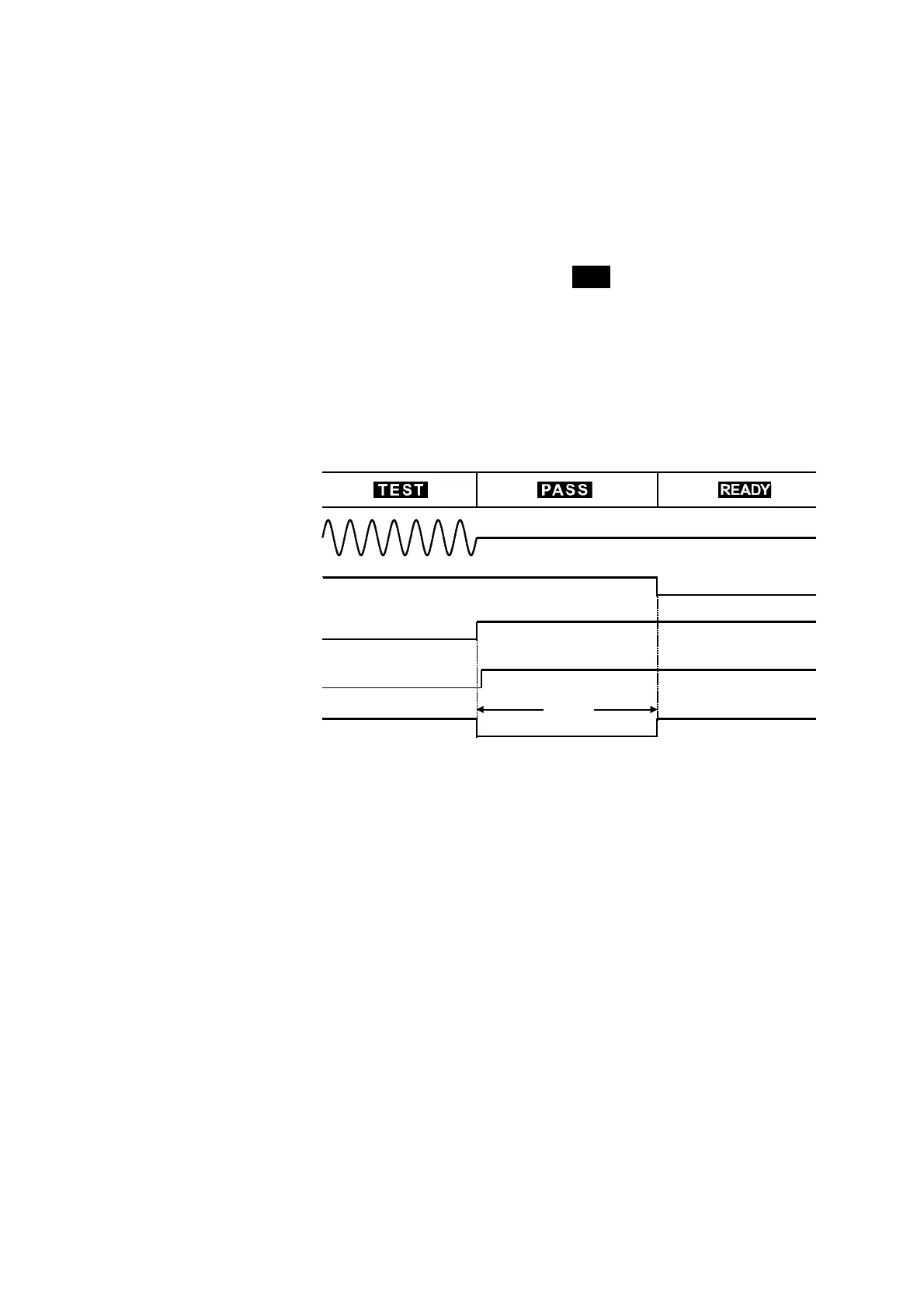
(2) Timing chart during a test decision
The figure shows the timing chart of the unit in PASS state after a test. In
PASS state, the
TEST
―――――――
signal indicates HIGH level.
The
H.V.ON
――――――――――
signal remains at LOW level provided that the voltage between
the output terminals remains unchanged, as the signal is synchronized with
the DANGER lamp. (Below 0.03 kV when performing a withstand voltage
test, or below 50 V when performing an insulation resistance test) Once the
voltage reaches 0, the signal changes to HIGH level.
The
PASS
―――――――
signal changes according to the
PASS
indicator on the fluorescent
display. If the PASS hold function is enabled, the
PASS
―――――――
signal continues to
indicate LOW level until the function is disabled.
When the Hold function is disabled or the unit automatically returns to the
READY state, the
PASS
―――――――
signal becomes HIGH level and the
READY
――――――――――
signal
becomes LOW level.
Withstand voltage mode