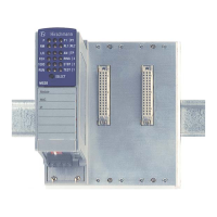
Installation EAGLE20/30
Release
06
04/2014
25
1.7.2 Additional status information
1.7.3 Input
1.7.4 Port state
These LEDs display port-related information. During the boot phase, they
indicate the status of the boot process.
The LEDs are directly located on the ports.
1.8 Management interfaces
1.8.1 V.24 interface (external management)
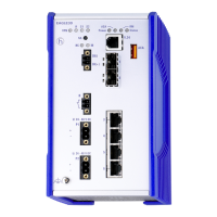
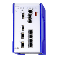
Note: For information about the position on the device see “Front view” on
page 20.
A serial interface is provided on the RJ11 socket (V.24 interface) for the local
connection of an external management station (VT100 terminal or PC with
corresponding terminal emulation). This enables a connection to the
Command Line Interface (CLI) and the system monitor to be made.
LED Display Color Activity Meaning
VPN
RD
S1
S2
(no function in the existing device version)
LED Display Color Activity Meaning
IN (no function in the existing device version)
Display Color Activity Meaning
Link status — None Device detects an invalid or missing link
Green Lights up Device detects a valid link
Flashes 1 time a period Port is switched to stand-by
Flashes 3 times a period Port is switched off
Yellow Flashing Device is transmitting and/or receiving data
VT 100 terminal settings
Speed 9,600 Baud
Data 8 bit
Stopbit 1 bit

 Loading...

