the right 0,539" (13,7 mm) above the separating line.
On
older
types
of
the motor these markings are mis-
sing, therefore notches must
be
made
at
the
correct
spots
(fig. 18).
Turn the
fly
wheel so,
that
the
0.
T. marking coitl-
cides with the
left
notch on
the
crankcase (171)
or
with
the separating line (22). From
th
is position turn
about
45
° towards
left
(opposite
the rotary di
rectioo1
of
the
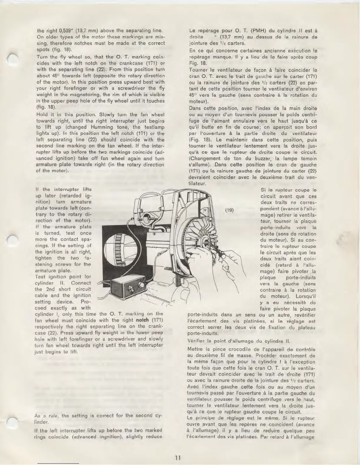
motor). In
this
posit
ion press upward
best
with
your right
forefinger
or
with a screwdriver
the
fly
weight
in
the magnetoring, the rim
of
which is visible
in
the
upper
peep hole
of
the
fly
wheel until it touches
(fig.
18).
Hold
it
in
this
position. Slowly turn the fan wheel
towards
right, until the right
interrupter
just
begins
to
lift
up (changed Humming tone,
the
testlamp
lights
up). In
this
position the
left
notch (171)
or
the
left
separating line (22) should
coincide
with the
second
line marking
on
the
ian
wheel.
If
the inter-
rupter
lifts
up
before
the
two
markings
coincide
(ad-
vanced
ignition)
take
off
fan wheel again and turn
armature
plate
towards
right
(in
the
rotary
direction
of
the
motor).
If
the
interrupter
lifts
up
later
(retarded
ig-
nition)
turn
armature
plate
towards
left
(con-
trary
to
the
rotary
di-
rection
of
the motor).
If
the
armature plate
is turned,
test
once
more the
contact
spa-
cings.
If
the
setting
of
the i
gnition
is all right,
tighten
the
two
fa-
stening screws
for
the
armature plate.
Test
ignition
point
for
cylinder
II.
Connect
the
2nd
short
circuit
cable
and
the
ignition
setting device. Pro-
ceed
exactly
as with
cylinder
l,
only
this
time
the
0.
T.
marking on
the
fan wheel must
coincide
with the
right
not
ch
(171)
respectively the
right
separating line on
the
crank-
case (22). Press upward
fly
weight
in the
lower
peep
hole
with
left
forefinger
or
a screwdriver and slowly
turn fan wheel towards
right
until
the
left
interrupter
just
begins
to
I
itt.
As a rule, the setting is
correct
for
the second cy-
linder.
If
the
left
interrupter
lifts up before the
two
marked
rings
coincide
(advanced ingnition),
slightly
reduce
11
Le reperage
pour
0.
T. (PMH) du cylindre II est a
droite
" (13,7 mm) au dessus
de
Ia rainure
de
jointure
des
1
/2
carters.
En
ce
qui
concerne
certaines ancienne execution !e
reperage manque.
II y a lieu de
le
faire
apres coup
Fig.
18.
Tourner le ventilateur de
fac;on
a faire
coincider
le
cran
0.
T.
avec le
trait
de
gauche sur
le
carter
(171)
ou Ia rainure
de
jointure
des
1
/e
carters (22) en par-
tan!
de
cette position tourner le ventiiateur d'environ
45
° vers Ia gauche (sens contraire a Ia rotation du
moteur).
Dans
cette
position, avec !'index
de
Ia main droi
te
ou au moyen d'un tournevis pousser le
poids
centri-
fuge
de
l'aimant annulaire vers le haut jusqu'a
ce
qu'
il
butte
en fin de course; on aperc;oit son bord
par
l'ouverture a Ia partie
dro
i
te
du ventilateur
(Fig.
18). Le maintenir dans cette position, puis
tourner
le ventilateur lentement vers Ia
droite
jus-
qu'a
ce que le rupteur
de
droite
coupe
le
circuit.
(Changement de ton du buzzer, Ia lampe temoin
s'allume). Dans
cette
position
le
cran
de
gauche
(171) ou Ia rainure gauche de
jointure
du
carter
{22)
devraient
coincider
avec
le
deuxieme
trait
du ven-
tilateur.
Si le rupteur
coupe
le
circuit
avant que ces
deux traits ne corres-
(19) pondent (avance a
l'afl~
mage)
retirer
le ventila-
teur, tourner
Ia plaque
porte-induits vers
Ia
droite
(sens de rotation
du moteur).
Si au
con-
traire le
rupteur
coupe
le
circuit
apres
que
les
deux traits aient
co·m-
cide
(retard a l'allu-
mage) faire
pivoter
Ia
plaque porte-induits
vers
Ia gauche (sens
contraire
a Ia rotation
du moteur). Lorsqu'il
y a eu necessite
de
faire
pivoter
Ia plaque
porte-induits
dans un sens ou un autre, reverifier
l'ecartement des vis
platinees, si le reglage est
correct
serrer les deux vis de fixation du plateau
porte-induits.
Verifier
le
point
d'allumage du cylindre II.
Mettre
Ia
pince
crocodile
de l'appareil
de
controle
au deuxieme fil
de
masse. Proceder exactement
de
Ia meme
fac;on
que pour le cylindre I a !
'e
xception
toute fois que
cette
fois
le cran
0.
T. sur
le
ventila-
teur
devrait
co·,ncider avec le
trait
de
droite
(171)
ou
avec Ia rainure
droite
de
Ia
jointure
des
1
h carters.
Avec
!'index gauche cette fois ou au moyen d'un
tournevis
passe
par
l'ouverture a Ia
partie
gauche du
ventilateur pousser le poids centrifuge vers
le haul,
tourner
le
ventilateur lentement vers Ia
droite
jus-
qu'a ce
que
le
rupteur gauche coupe le circuit.
Le
principe
de
reglage est le meme. Si le rupteur
ouvre avant que
les reperes ne co1ncident (avance
a l'allumage) il y a lieu
de
reduire quelque peu
l'ecartement des vis platinees. Par retard
a l'allumage
 Loading...