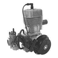
Fan wheel
6. Screw
holding
dev1ce
for
fan wheel W 116 (see
fig.
I) to the crankcase. Take
off
catch
with
locking
plate by
loosenmg
the fill. head screws Take
off
the
cover
plate
, lying behind the catch
loosen
the
heiC
nut
w1th
which the fan wheel
1st
fastened w;th hex.
spanner
(SW
24).
a)
Fan wheels
of
an
older
type with only 3
tapped
holes 6 mm
for
fastening
of
the catch.
Place
extroctorW
113
with the 3 hex screws
into the
3 threads
of
the fan wheel.
loosen
fly wheel by turning
the pressing screw
of
the
extractor
towards
the right. Take
off
hold1ng dev1ce so that
the fan wheel can be
taken
off
(fig. I)
b) Fan wheels with 3
lld-
ditional
tapped
holes
8 mm.
Screw
off
holding
de-
VICe
W 116. Firmly
screw
extractor
W 120
to
the hub
of
the fan
wheel with the 3 hex
screws and take
off
fan wheel as shown
1n
f1gure
3.
Take
out
key in the crankshaft.
loosen
the
two
set
screws with which the arma-
ture pl1\te is screwed down in the housing.
Ignition
7.
Take
motor
out
of
the
v1se
and screw
off
assembly
angle iron.
22:
Screw
assembly angle
iron
as shown on figure
11
assembly
to
the
two
drive
side studs
for
the
cylinder
and again place
motor
into vise.
171: Place assembly angle irons W 115
over
the
two
tie rods on
the
drive
side and
tighten
by means
of
two
tubes 140 mm long and hex. nuts. Put
motor
back
into
vise (see fig. 9 assembly).
8.
Pull
off
protecting
cap
and spark plug
hood
as well
as the clamp on the 1gnihon cable and insulating
hose
loosen
the
4 tapp1ng screws with which the
ignition
coils
are fastened.
Pu'l
out
of
the sockets
of
the
ignition
coils
the
wire
plug
with
short
circuit
and
generator
cable. Then
the
two
ignition
coils
can be
pulled
off
with
ignition
cable
and the insulating hose
pulled
over
them
Take
off
rainprotection
capes and insulating
hosM
from the
generator
and
short
circuit
cables. Then
the
two
cables
belonging
together
(short
circuit
and
one
generator
cable
each) can be
pulled
through the
boring
in the housing
into
the
ignition
space.
After
pulling
out
the
light-,
ground-
and short
circuit
cables
2
Ventilateur
6.
Fixer
le
d1spositif de
blocage
du venttlateur W 116
commo indique Figuro 1, devisser los vis a 6 pans
creux,
retirer
l'entraineur
et
Ia
tole
frein
d'ecrou;
re-
tirer
Ia
tole
de
recouvrement so trouvant
derriere
l'entraineur. Devisser l
'e
crou a 6 pans fixant
le
ven-
tilateur
au moyen
de
Ia cle plate de
24
mm.
a)
Ventilateur
d'execution
plus
ancienne avec seule-
ment 3 trous taraudes
pour
Ia fixation
de
l'en-
traineur
.
(Filetage
de
6 mm).
(3)
171
Monter
l·extracteur W 113
en vissant
les
trois
bou-
lons de l·extractP.ur dans
les
trois
trous sur le mo-
yeu du ventilateu
r.
Arra-
cher le
ventilateur
en
tournant
Ia
v1s
de
pres-
sion de l'extracteur
vcrs
Ia
droite
Demonter
le
dispositif
de
blocage
du ventila-
teur
afin
de
pouvoir
en·
lever
celui-ci.
Fig. 1
b)
Ventilateur
avec 3
trous
taraudes supplementai-
res
(Filetage
de
8 mm).
Demonter le
dispositif
de
blocage
du
ventila-
teur
W 116
Monter
l'ex-
tracteur
W 120 en
le
vis·
san! au · moyeu par les
trois vis
a 6 pans.
Arra-
cher le ventilateur
COI"lmC
indique.
Fig.
3.
Reltrer Ia
clavette
Woodruff
de
Ia
rainure du vile-
brequtn. Devisser les 2 vis fixant le plateau
porte-
induits au carter.
Allumage
7. Retirer
le
moteur de l'etau, enlever le gabari.
22: Fixer le gabari comme indique
figure
11
aux deux
goujons
cote
prise
de force.
Replacer
le moteur dans
l'etau
171 : Passer
le
gabari
W 115
sur
les deux
goujons
de
cylindre
cote
prise
de force,
le
serrer au moyen
de
deux
bouts
de
tube
de
140
mm
et
des
ecrous a
6 pans.
Replacer
le moteur dans l'etau.
(voir
Fig. 9
montage)
8.
Demonter
Ia
co1ffe de
protection
, le chapeau de
bou·
g1e
ainsi
que
Ia
bride
de f1xation
du
fil
de bougie
ct
Ia
gaine isolante
Dev1sser les 4 vis taraud fixant les bobines d'allu-
mage.
Retirer
de
leur
prise
sur
Ia
bobine
les fiches avec
les fils
coupe
circuit
et
les
fils
de
Ia
generatric\3.
les
deux bobines avec
les
fils d'allumage
et
les
ga nes isolantes peuvent maintenant
etre retirees.
Retirer le capuchons pare-pluie et les gaines
ISO·
lantes des fi ls de Ia generatrice
et
du coupe
circuit.
Par
Ia
suite on
pourra
retirer
les
deux paires
de
fils
(1
coupe
c~rcu
t 1
generatnce)
du caoutchouc passe
cable
du
carter
en les passant cote altumage. Apres
avoir
retire les fils lumii!re, masse
et
coupe
c rcuot
 Loading...