GH F33 BDA
Pay attention that in standing position of the diaphragm pump the outlet is at the top. Place
fuel connecting piece is perceptible by marking (→)on the case.
The centrically connection the diaphragm pump is an impulse connection. The impulse line
from the crankcase to the diaphragm pump should be as short as possible. For selection of
impulse and fuel line it should be noticed that inflexible lines that will not extend under
pressure should be used. Impulse line should have a maximum length of 150 mm and not
exceed a minimum inside diameter of 6 mm.
In every case it is advantageous if fuel tank is positioned above the engine, as so there is
guaranteed some pressure of the fuel supply. The use of diaphragm pump is recommended
additionally. A suitable measure instrument should control fuel pressure in any case.
For installation of fuel tank below the engine, the following geometrical dates should be
noted.
The maximum length intake manifold between fuel tank and diaphragm pump should not
exceed 2000 mm at a minimum inside diameter of 6 mm. At this a altitude of 1 m has not to
exceed. During the running the possible inclination of complete equipment has to be
considered (ascent / down fly of fly equipments, uphill/ downhill with ground equipments,
….)
The maximum length of the pressure line should not exceed 500 mm at inside diameter of 6
mm. At this a maximum pressure altitude between diaphragm pump center and floater case
center of the carburettor should not be exceed.
If diaphragm pump should be installed at engine, it should be mounted this way that
diaphragm is vertical to crankshaft axle (wear or ignition side). Herewith it is guaranteed that
vibrations at crankshaft axle due to the engine not impair the action and function of the
diaphragm pump due superimposition of the vibrations.
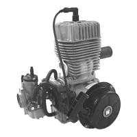
1.2.3-2 F 33 B
The fuel supply of engine F 33 B is completely provided by diaphragm carburettor. Inside the
carburettor is integrated a diaphragm pump that provides carburettor with sufficient fuel every
time.
The diaphragm pump that is integrated in the case of diaphragm carburettor is connected with
the crankcase by a connecting hose and so with pressure pulsation of the engine. Because of
the existing pulsation, fuel is sucked from the fuel tank through a fuel filter. The carburettor
extracts the needed volume of fuel that is provided by diaphragm pump concerning the
adjusted idle and load. The rest is pumped back by a return line into fuel tank.
1.2.4 Carburettor control
The throttle slide control of variable jet as well as diaphragm carburettor is handled by
bowden cables. At idle running (throttle slide is seated on screw for idle; screw for idle of idle
stop throttle strike against idle stop) bowden cable should have some space so that throttle
slide can reach idle position secured.
At full throttle the slide has to release the whole cross section of carburettor
1.2.5 Adjustment of idle speed
Adjustment of idle speed should be done with warm engine. If engine runs up, adjust the
wanted idle speed by twisting the screw for idle. Twisting clockwise rises idle speed, twisting
anti-clockwise reduces idle speed. Screw for idle is fixed through a spring that prevents
undesirable wrench of the adjusting screw.
Stand: 02.02.05 DOC_F33_B_E_0.01