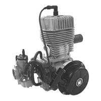
GH F33 BDA
Illustration 1.1.1-2 (Engine F 33 B)
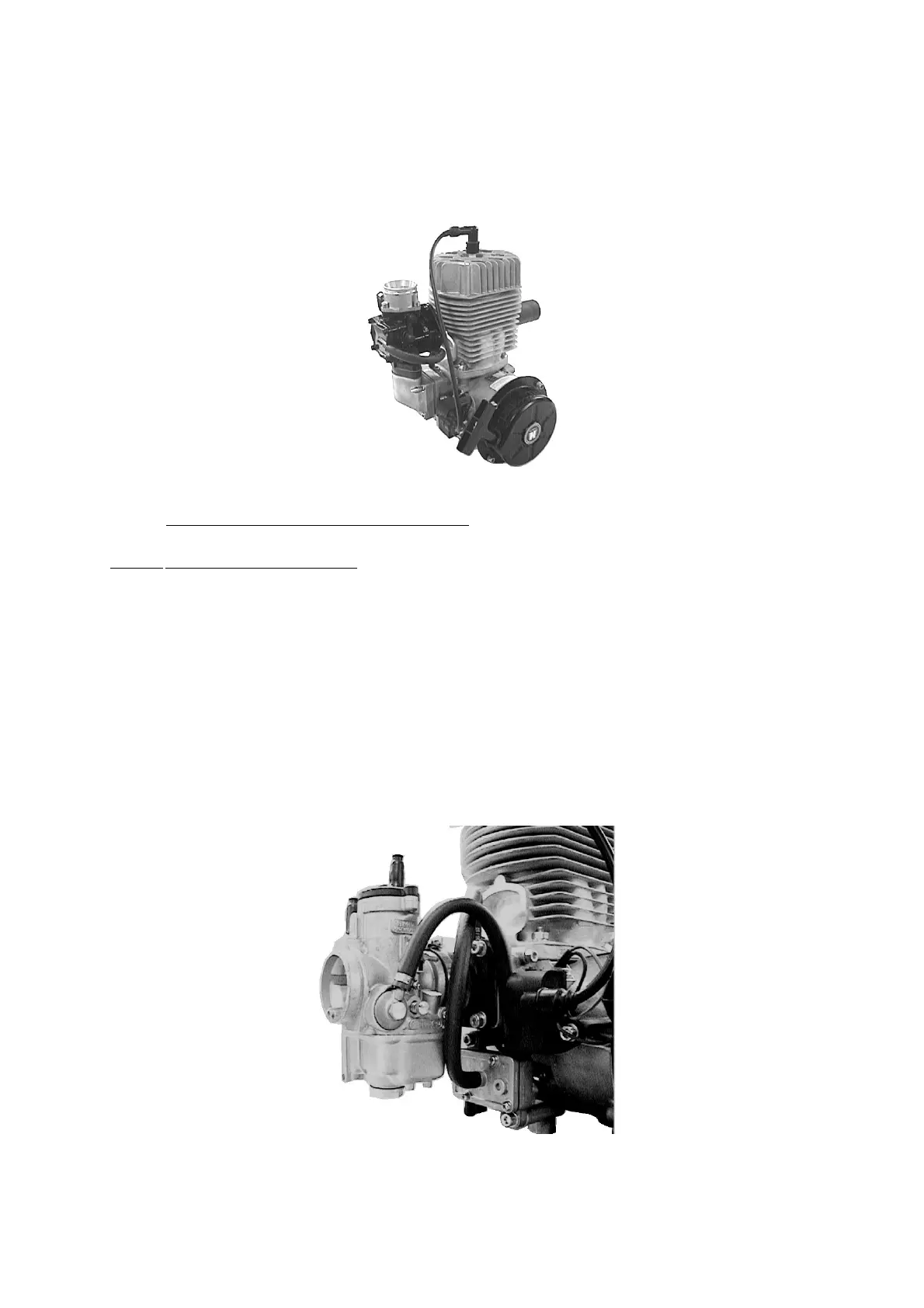
1.1.2 Description of the fuel mixture system
1.1.2-1 Variable jet carburettor
The fuel mixture system (Illus. 1.1.2-1) of the engine F 33 A consists of a variable jet
carburettor. The carburettor is linked with intake window and the inlet diaphragm of
crankcase by a rubber flange. On this occasion the rubber flange is screwed with cylinder
screws and locking discs and the carburettor is tightened by a clamp in the rubber flange.
On the inlet side of carburettor is positioned a dry air filter which is tightened on the
carburettor by a clamp.
Illustration 1.1.2-1 (Fuel mixture system with variable jet carburettor)
Stand: 02.02.05 DOC_F33_B_E_0.01