Do you have a question about the Hisense AMW2-20U4SZD1 and is the answer not in the manual?
| Brand | Hisense |
|---|---|
| Model | AMW2-20U4SZD1 |
| Category | Air Conditioner |
| Language | English |
Detailed technical specifications for indoor and outdoor units, covering capacity, electrical data, dimensions, and piping.
Specifications for key components like indoor fan motors, outdoor fan motors, and compressors.
Specifications for other components such as inductors, filters, and stepper motors.
Visual representations and dimensions for various indoor unit models.
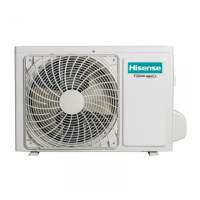
Visual representations and dimensions for various outdoor unit models.
Diagrams illustrating the refrigerant flow for different model series during operation.
Step-by-step guide for evacuating the refrigerant system.
Guidelines on maximum refrigerant pipe length and height difference for optimal performance.
Wiring schematics for indoor and outdoor units, detailing connections for various components.
Information on indoor and outdoor control boards, including component identification and diagrams.
Data tables for temperature sensors, detailing resistance and voltage readings at different temperatures.
Covers operational parameters, controller functions, and modes like Timer, Sleep, and Dehumidifying.
Details outdoor unit operation, performance indices, protections, modes, and valve controls.
Lists and explains error codes for indoor and outdoor units, including fault descriptions and root causes.
Procedures and tools for checking the refrigerant system's pressure and flow.
Guides for inspecting and testing components like fan motors, compressors, inductors, fuses, and capacitors.


 Loading...