EasyManua.ls Logo

Hisense AVA-30UXCSCH-70 - User Manual

Hisense AVA-30UXCSCH-70
19 pages
Print Icon
To Next Page IconTo Next Page
Loading...
9
9
P00430Q
ORIGINAL INSTRUCTIONS
ALL
3RZHU
6RXUFH
+]
AIR TYPE
AVA-30UXCSCH-70
AVA-48UXCSQH-108
AVA-76UXCSRH-168
AVA-96UXCSRH-210
1+]
AVA-114UX6SRH-300
FRESH
Type
Model
Question and Answer IconNeed help?

Do you have a question about the Hisense AVA-30UXCSCH-70 and is the answer not in the manual?

Summary

Safety Summary and Precautions

General Installation Warnings

Critical warnings for installation, piping, and electrical wiring without manual reference.

Operational Cautions for Safe Use

Guidelines for appliance use by children and individuals with limitations, and installation location advice.

Structure and Installation Tools

Necessary Tools and Instruments for Installation

A comprehensive list of tools and instruments required for the proper installation of the unit.

Transportation and Handling Guidelines

Product Transportation Procedures

Instructions for transporting the product to the installation site as close as possible before unpacking.

Indoor Unit Handling Precautions

Warnings against introducing foreign material into the indoor unit and precautions to prevent damage to insulation.

Indoor Unit Installation Procedures

Indoor Unit Installation Safety

Critical safety advice to prevent fire, explosion, or falls during indoor unit installation.

Factory-Supplied Accessories Overview

A list of accessories provided with the indoor unit for installation purposes.

Initial Installation Checks

Ensuring proper clearance, air distribution, and avoiding hazardous environments for installation.

Suspension Bolt Mounting

Detailed steps and diagrams for correctly mounting suspension bolts for the indoor unit.

Sling Bolt and Piping Connection Marking

Marking positions for sling bolts, refrigerant piping, and drain connections according to model dimensions.

Mounting the Indoor Unit

Step-by-step instructions with diagrams on how to hang the indoor unit securely.

Unit Level Adjustment

Procedures for ensuring the unit is level, considering foundation gradient and drain slope.

Supply Duct Connection

Guidelines for connecting supply ducts, including vibration proofing and heat insulation.

Refrigerant Piping Work

Refrigerant Piping Materials and Preparation

Selecting and preparing copper pipes, ensuring they are clean, dry, and free from dust.

Refrigerant Piping Connection Procedures

Steps for connecting refrigerant pipes, including capping, brazing, and protecting components.

Drain Piping Installation

Drain Piping Installation and Insulation

Fastening the drain hose, ensuring correct slope, and insulating the drain pipe.

Drain Piping Notes and Leak Checks

Important notes on preventing drain water backflow, avoiding sanitary connections, and checking for leaks.

Electrical Wiring and Checks

Electrical Wiring Safety Precautions

Essential safety measures for electrical wiring, including power off, protection from animals, and proper tightening.

General Electrical Wiring Checks

Verifying component selection, power supply voltage, wire capacity, and ground wire connection.

Electrical Wiring Connection Guide

Instructions for connecting remote control cables, power supply, earth wires, and indoor/outdoor units.

Test Run Procedure

Test Run Procedure and Safety Checks

Steps for performing a test run, including electrical checks, valve operation, and operational safety points.

Safety and Control Device Settings

Common Installation Parameters

Field Minimum Wire Sizes for Power Source

Guidelines and tables for selecting minimum wire sizes for the power source based on current.

Dip Switch Setting Procedures

Instructions for setting various dip switches for unit number, capacity, and refrigerant cycle.

Overview

This document provides the operation, installation, and maintenance manual for Hisense inverter-driven multi-split air conditioners (heat pump) for indoor units. It covers various models, including AVA-30UXCSCH-70, AVA-48UXCSQH-108, AVA-76UXCSRH-168, AVA-96UXCSRH-210, and AVA-114UX6SRH-300, designed for "ALL FRESH AIR TYPE" applications.

Function Description

The Hisense inverter-driven multi-split air conditioner is a heat pump system designed for standard air conditioning purposes, providing both cooling and heating. It is intended for indoor use and is capable of operating within a wide range of ambient temperatures. The system utilizes an inverter-driven compressor for efficient and precise temperature control. The manual emphasizes that the unit should not be used for other purposes such as drying clothes or refrigerating foods.

Important Technical Specifications

The indoor units are available in several models with different power sources and capacities:

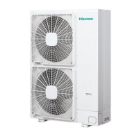
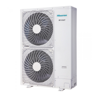
  • Models AVA-30UXCSCH-70, AVA-48UXCSQH-108, AVA-76UXCSRH-168, AVA-96UXCSRH-210: These models operate on a 220-240V, 50Hz power supply.
  • Model AVA-114UX6SRH-300: This model requires a 380-415V, 3N~50Hz power supply.
  • Operating Temperature Range: The indoor unit is designed to run between -7°C and 43°C.
    • Cooling Operation: 20°C to 43°C
    • Heating Operation: -7°C to 15°C
    • The indoor unit will stop operating if the outside temperature falls below -7°C.
  • Refrigerant: The manual specifies the use of R410A refrigerant, emphasizing that suitable equipment (vacuum pump, gas hose, charging cylinder, gauge manifold) must be used for R410A and not mixed with other refrigerants.
  • Piping Connections:
    • Models 30 & 48: Refrigerant gas pipe connection is 15.88mm (5/8 inch), and refrigerant liquid pipe connection is 9.53mm (3/8 inch).
    • Model 76: Refrigerant gas pipe connection is 19.05mm (3/4 inch), and refrigerant liquid pipe connection is 9.53mm (3/8 inch).
    • Model 96: Refrigerant gas pipe connection is 22.2mm (7/8 inch), and refrigerant liquid pipe connection is 9.53mm (3/8 inch).
    • Model 114: Refrigerant gas pipe connection is 25.4mm (1 inch), and refrigerant liquid pipe connection is 12.7mm (1/2 inch).
    • All models use a VP 25 drain pipe connection.
  • Electrical Wiring:
    • Fuse Capacity for Control Circuit: 5A for all models.
    • Evaporator Fan Motor Thermostat:
      • Cut-Out: 130±5°C (30-96 models), 145±5°C (114 model)
      • Cut-In: 83±15°C (30-96 models), 80±15°C (114 model)
    • Freeze Protection Thermostat:
      • Cut-Out: 0°C for all models.
      • Cut-In: 14°C for all models.
    • Thermostat Differential: 2°C for all models.
    • Minimum Wire Sizes for Power Source (EN60335-1):
      • Models 30 (1.2A): Power source cable 2.5mm², transmitting cable 0.75mm².
      • Models 48 (2.5A): Power source cable 2.5mm², transmitting cable 0.75mm².
      • Models 76 (5.2A): Power source cable 2.5mm², transmitting cable 0.75mm².
      • Models 96 (6.0A): Power source cable 2.5mm², transmitting cable 0.75mm².
      • Models 114 (2.7A, 3N~50Hz): Power source cable 2.5mm², transmitting cable 0.75mm².
      • For currents exceeding 63A, cables should not be connected in series.
  • Installation Clearances:
    • Models 30-48: Service access panel ≥450mm, front side ≥130mm, other sides ≥600mm, top ≥1000mm.
    • Models 76-114: Service access panel ≥600mm, front side 150-200mm, other sides ≥800mm, top ≥1000mm.

Usage Features

  • Safety First: The manual stresses the importance of reading and understanding the manual before use, and keeping it for future reference. It includes clear warnings and cautions regarding potential hazards, such as severe personal injury, death, or property damage.
  • Proper Installation: Installation should be performed by qualified personnel, following local regulations and standards (e.g., British Standard BS4434 or Japan Standard KHKS0010). The unit must be installed in a location with sufficient strength to support its weight and away from strong electromagnetic wave radiators.
  • Air Distribution: Consider the air distribution within the room to ensure uniform temperature. Avoid obstacles that may hinder airflow.
  • Environmental Considerations: Do not install the unit in flammable environments, outdoors, or in areas with oil vapor/mist, acid, or alkaline substances, as these can reduce performance or damage the unit. Special precautions are advised for installations near medical equipment to prevent electromagnetic interference.
  • Children Safety: The appliance is not intended for use by children or persons with reduced physical, sensory, or mental capabilities without supervision. Children should be supervised to ensure they do not play with the appliance. The appliance should not be installed in a laundry room.
  • Duct Connection: The supply duct should be connected using canvas ducts to minimize sound vibration. Duct material should be non-flammable. Heat insulation is required for dew protection. Proper duct design is crucial to prevent excessive noise and splashing.
  • Dip Switch Settings: The PCB in the indoor unit has 8 types of dip switches and rotary switches for various settings, including Unit No. Setting (DSW6&RSW1), Refrigerant Cycle No. Setting (DSW5&RSW2), and Fuse Recover (DSW7). These must be set correctly during installation for proper operation.

Maintenance Features

  • Regular Checks: Before electrical wiring work or periodical checks, the main power switch to both indoor and outdoor units must be turned OFF, and fans must have stopped.
  • Leakage Test: Do not use oxygen, acetylene, or other flammable/poisonous gases for leakage tests. Compressed air, nitrogen, or refrigerant are recommended.
  • Drain Piping: Ensure drain piping has a downward slope (1/25 to 1/100) to prevent water backup and leakage. Do not connect to sanitary or sewage piping. Insulate the drain pipe after connection.
  • Electrical Safety:
    • Ensure the ground wire is securely connected.
    • Use fuses of specified capacity.
    • Check electrical resistance (more than 1 megohm) between ground and electrical parts.
    • Verify power supply voltage is within ±10% of the rated voltage.
    • Confirm the capacity of electrical wires.
    • Install a multi-pole main switch with a space of 3.5mm or more between each phase.
    • Tightly secure wires with cord clamps inside the electrical box.
    • Protect wires, drain pipes, and electrical parts from rats or other small animals to prevent damage or fire.
    • Wrap accessory packing around wires and plug wiring connection holes with seal material to protect against condensate water or insects.
  • Test Run: A test run must be performed according to the "Installation & Maintenance Manual" of the outdoor unit. Ensure stop valves are fully open and the main power source has been ON for at least 12 hours to warm compressor oil.
  • Handling Refrigerant Pipes: Cut pipe ends before brazing to remove the cap and discharge gas. When brazing, cover adjacent insulation pipes with a wet cloth to protect thermistors from heat damage.
  • Insulation: After brazing, insulate pipes, ensuring the space between insulating pieces is covered.
  • Auxiliary Drain Pan: If relative humidity exceeds 80%, an auxiliary drain pan (field-supplied) should be installed beneath the indoor unit.
  • Disposal: The product should be disposed of responsibly through designated collection systems to promote sustainable reuse and prevent environmental or health harm.

Hisense AVA-30UXCSCH-70 Specifications

General IconGeneral
BrandHisense
ModelAVA-30UXCSCH-70
CategoryAir Conditioner
LanguageEnglish

Related product manuals