Do you have a question about the Hisense AVWT-76FESRA and is the answer not in the manual?
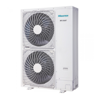
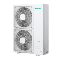
Lists available outdoor unit models and their capacities.
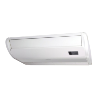
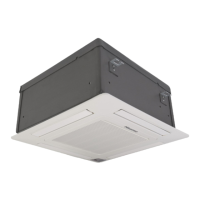
Details compatibility of indoor units with outdoor units.
Defines standard connection capabilities for outdoor units.
Explains Hisense centralized and smart home management systems.
Illustrates the piping layout and connection details.
Specifies the working conditions for cooling and heating operations.
Details the physical dimensions of outdoor units.
Provides dimensional data for the switch box.
Illustrates the internal structure and component layout of outdoor units.
Specifies the required clearance around outdoor units for installation.
Shows cooling/heating capacity vs. combined indoor unit horsepower.
Provides cooling capacity data across various temperature conditions.
Provides heating capacity data across various temperature conditions.
Explains how to adjust capacity based on piping length.
Provides correction factors for heating capacity during defrost.
Lists electrical specifications, including power supply and protection devices.
Presents noise criteria curves for various models.
Illustrates the refrigerant flow for outdoor units.
Explains the functions of various control devices in different operation modes.
Covers function selection via switches, input/output signals, and safety devices.
Provides flowcharts for cooling, dry, and heating operations.
Shows the structure of the outdoor unit and its refrigerant cycle diagram.
Lists essential tools and instruments for installation.
Details procedures for transporting the unit before installation.
Explains safe methods for lifting and hanging the unit.
Lists accessories provided with the outdoor unit for installation.
Provides general guidelines for installing the outdoor unit.
Specifies required space for maintenance (see Section 4.1).
Details requirements for a stable and correct foundation.
Explains how to manage condensed water during operation.
Specifies required piping materials and selection criteria.
Details the correct procedure for flaring pipes and using connectors.
Provides important warnings for outdoor unit piping installation.
Explains how to connect refrigerant pipes to outdoor units.
Specifies pipe diameters for base outdoor units.
Provides pipe diameters for two-unit outdoor combinations.
Details pipe diameters for three-unit outdoor combinations.
Explains the correct operation and handling of stop valves.
Outlines preliminary checks for electrical components and wiring.
Provides wiring diagrams and general warnings for electrical work.
Details electrical wiring procedures specific to outdoor units.
Explains how to connect wiring between various units and the switch box.
Explains the procedure for performing an air-tight test on the system.
Details the process of vacuum pumping the refrigerant system.
Provides methods for calculating and determining additional refrigerant needed.
Describes the correct procedure for charging refrigerant into the system.
Explains how to use the system for automatic refrigerant amount checks.
Discusses refrigerant gas leakage and calculation of permissible concentration.
Explains the purpose and layout of switches and LEDs on PCBs.
Details the specific functions and settings of switches and LEDs.
Guides on checking the functionality of main components via remote control.
Outlines checks for other components like transistor modules and capacitors.
Explains how to configure communication settings for the Hi-NET system.
Lists essential checks to perform before starting the test run.
Provides instructions for conducting a test run using the wired controller.
Describes how to perform a trial operation directly from the outdoor unit.
Provides a general overview of inspection points for system activation.
Details the steps for performing spot inspections using the remote control.
Lists items for spot inspection and their corresponding display indications.
Provides detailed troubleshooting steps for various alarm codes and phenomena.
Explains how to use detection modes for troubleshooting via the 7-segment display.
Displays saturation curves for different refrigerants.
Provides a Mollier chart for R410A refrigerant.
| Brand | Hisense |
|---|---|
| Model | AVWT-76FESRA |
| Category | Air Conditioner |
| Language | English |