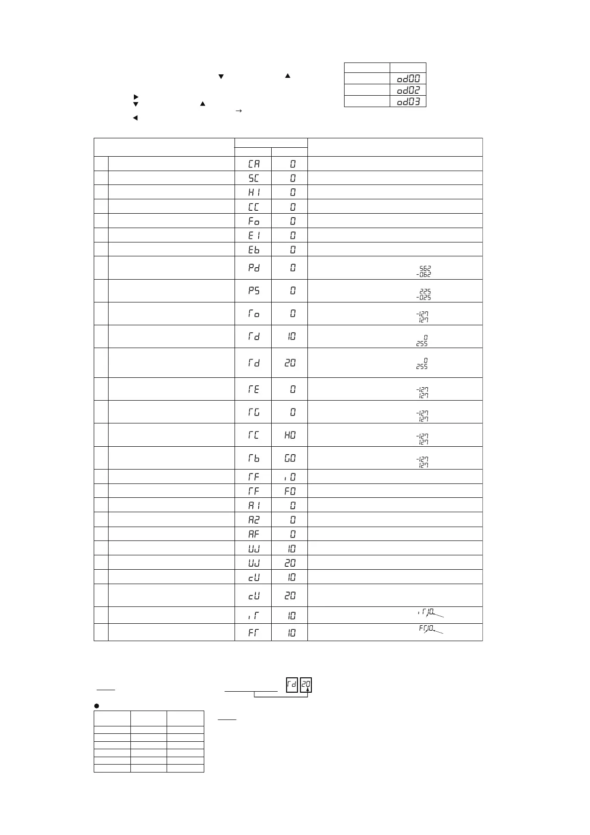
Select the outdoor combination unit No. for indication.
When the selection is changed, press PSW4 ( ) to forward or PSW2 ( ) to backward.
*1) The indicated current is reduced value. Use a clamp meter for the accurate current value.
*2) For resetting the accumulated operation time, press “PSW1 + PSW3” for 5 seconds while the accumulated data is displayed.
(C) Outdoor Unit Information
Outdoor Unit Capacity
Outdoor Expansion Valve
MV1 Opening
Outdoor Expansion Valve
MVB Opening for Bypass
Expansion Valve Opening for Bypass Indication (Unit: %)
Unit Capacity Indication
Refer to “Outdoor Unit Capacity Table”
Output State of Outdoor Micro-Computer Indication
Refer to “Location of Push Switches and 7-Segment Display”
2 Output State of Outdoor Micro-Computer
Running Frequency of
Inverter Compressor MC1
4
3
Total Number of Running Compressor Total Number of Running Compressor Indication
6
5 Air Flow Rate
Details of Indication
Air Flow Rate Indication (0 to 25 Steps)
Outdoor Expansion Valve MV1 Opening Indication (Unit: %)
Running Frequency of INV. Compressor Indication (Hz)
16
15
Evaporating Temperature
TE at Heating
Discharge Gas Temperature
on the Top of Compressor MC1 (TD1)
Discharge Gas Temperature
on the Top of Compressor MC2 (TD2)
14
13
Accumulated Operation Time of
Compressor MC1
Accumulated Operation Time of
Compressor MC2
Accumulated Operation Time of
Compressor MC1
Accumulated Operation Time of
Compressor MC2
Compressor MC1 Current
*1)
Compressor MC2 Current
*1)
Fan Motor (MFO1) Current
*1)
20
21
18
17
19
Inverter Fin Temperature
22
27
26
25
23
24
Discharge Pressure (High)
Suction Pressure (Low)
10
12
Ambient Air Temperature (Ta)
7
8
11
9
Unit: Hour (Indication x 10 Hours)
Refer to “Inverter
Stoppage Cause Table”
Refer to “Fan Controller
Stoppage Cause Table”
Unit: Hour (Indication x 10 Hours)
AVWT-136 to AVWT-170 only
Unit: Hour (Indication x 10 Hours)
Accumulated operation time can be reset.
*2)
Unit: Hour (Indication x 10 Hours)
AVWT-136 to AVWT-170 only
Accumulated operation time can be reset.
*2)
Unit:
o
C
Unit:
o
C
Unit: A
Unit: A
Unit: A
AVWT-136 to AVWT-170 only
Outdoor Heat Exchanger
Gas Temperature
Supercooling Temperature
Supercooling Temperature at Bypass
Fan Controller Fin Temp.
Select the outdoor combination unit No. for indication by pressing PSW4 or PSW2.
Press PSW3 ( ) for details information.
Press PSW4 ( ) to forward or PSW2 ( ) to backward.
The information will be indicated alternately as “Item” “Details”
Press PSW5 ( ) for return to Outdoor Combination Unit No. Selection.
Cause of Inverter Stoppage
Cause of Fan Controller Stoppage
(Example)
SEG2 SEG1
NOTE: The outdoor unit No. is indicated on the one digit of “SEG1” .
Unit
Unit A (No.0)
Unit B (No.2)
Unit C (No.3)
Indication
Unit:
o
C
Indication of Thermistor Open Circuit:
Indication of Thermistor Short Circuit:
Unit:
o
C
Indication of Thermistor Open Circuit:
Indication of Thermistor Short Circuit:
Unit:
o
C
Indication of Thermistor Open Circuit:
Indication of Thermistor Short Circuit:
AVWT-136 to AVWT-170 only
Unit:
o
C
Indication of Thermistor Open Circuit:
Indication of Thermistor Short Circuit:
Unit:
o
C
Indication of Thermistor Open Circuit:
Indication of Thermistor Short Circuit:
Unit:
o
C
Indication of Thermistor Open Circuit:
Indication of Thermistor Short Circuit:
Unit:
o
C
Indication of Thermistor Open Circuit:
Indication of Thermistor Short Circuit:
Unit: MPa
Indication of Thermistor Open Circuit:
Indication of Thermistor Short Circuit:
Unit: MPa
Indication of Thermistor Open Circuit:
Indication of Thermistor Short Circuit:
Outdoor Unit Capacity Table
NOTE:
In case of combination unit, the indication of outdoor unit capacity is
total capacity of constitution units.
1
Item Details
SEG1SEG2
7-Segment Display
Indication
kBtu/h
Capacity
(kW)
64 22.4 76
80 28.0 96
96 33.5 114
112 40.0 136
128 45.0 154
144 50.0 170
Comp. No.
O.U. No.
Fan Controller No.
O.U. No.
 Loading...