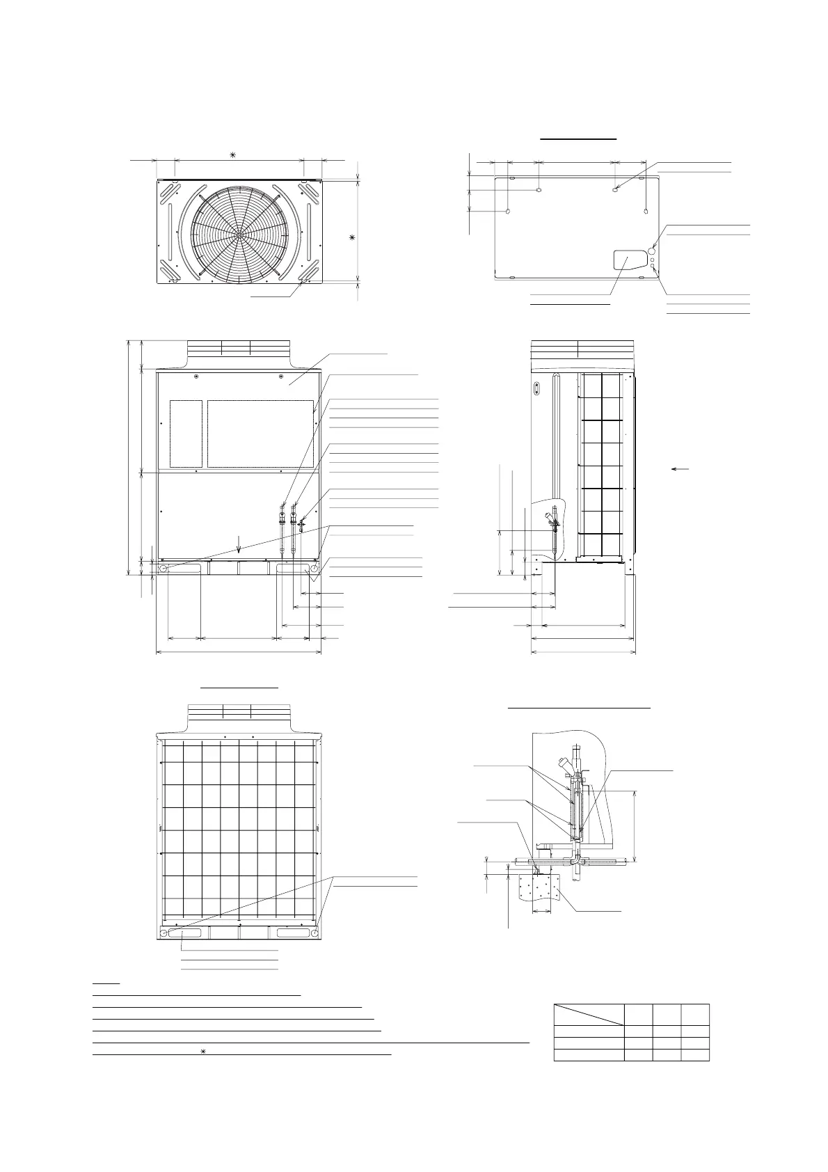
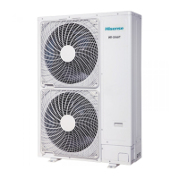
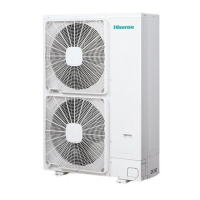
Model: AVWT-114*,AVWT-136*,AVWT-154*
Unit: mm
Field Installation (Example)
P
Q
(Standard)
(Rear Side)
(Front Side)
25.4
28.6
22.2
22.2 12.7
12.7
15.88
28.6
22.2
Viewed from P
Viewed from Q
Hole for
Refrigerant Piping
(245 x 138)
98 227 560 227
105157
Hole for
Condensate Drain
(Ø26 x 4)
Hole for
Power Supply Wiring
(Ø52)
Holes for
Control Line or
Power Supply Wiring
(Ø26 x 2)
100
180 Gas Line
325 Liquid Line
170 Gas Line
175 Liquid Line
765
750
78 608
640 767 213
1720
145
205
285
88
1210
20 60
100
558 238238
Service Cover
Gas Line Refrigerant
Piping Connection
(Low Pressure)
ØA Field-Supplied Pipe Size
Gas Line Refrigerant
Piping Connection
(High Pressure)
ØB Field-Supplied Pipe Size
Liquid Line Refrigerant
Piping Connection
ØC Field-Supplied Pipe Size
Hole for
Power Supply Wiring
(Ø52 x 2)
Electrical Control Box
Hole for
Refrigerant Piping and
Control Line Wiring
4-Holes
(38 x 15)
729
18 18
131
948
131
(276)
50
less than 30
Brazing
Concrete
Foundation
70
Insulation
Accessory Pipe
Anchor Bolt
(M12)
Hole for
Refrigerant Piping and
Control Line Wiring
Model
Dimension
A B C
AVWT-114*
AVWT-136*
AVWT-154*
NOTES:
1. Drain water is discharged from the unit during the operation.
a. Choose a place where well drainage is available. Provide a groove for drain.
b. Do not provide an upward slope from the unit to avoid reverse flow of the drain.
Provide a second drain pan under the outdoor unit, to collect drain water securely.
c. Do not use the drain boss (optional) in a cold area. (Drain water in the drain pipe may be frozen and the drain pipe may crack.)
2. The dimensions marked with indicates the mounting pitch dimension for anchor bolts.
Hole for
Power Supply Wiring
(Ø52 x 2)
Heat Recovery System (3 Pipes)



 To Next Page