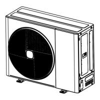
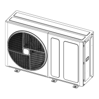
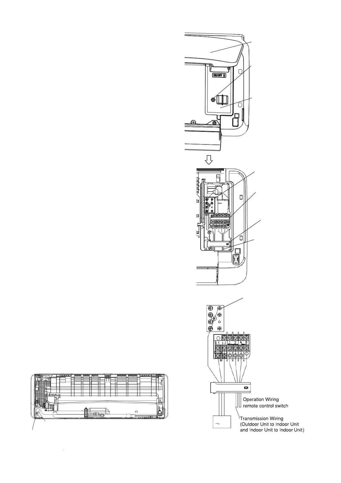
is shown in Fig. 7.1.
(1) Unscrew and remove the conduit mounting
plate from the machine base. Fix a conduit for
power supply wiring to the plate with a lock nut and
reattach them at original position.
(2) Connect the cable of an optional remote
control switch to A, B terminals of the TB(terminal
board) inside the electrical box through the
connecting hole in the cabinet.
(3) Connect the wires between the indoor unit and
the outdoor unit to 1,2 terminals of the terminal
board inside the electrical box through the
connecting hole in the cabinet.
(4) The power supply and earth wires must be
installed correctly. Please connect to the power
circuit with a ELB.
(5) Tightly clamp the wires using the cord clamp.
TB for Power Supply(L1 L2)
and Transmission wiring(1 2)
and Remote control switch(A B)
TP(terminal plate) for Earth wire
17
7.1 General Check
(1) Make sure that the field-supplied electrical
components (main power switches, circuit breakers,
wires, conduit connectors and wire terminals) have
been properly selected according to the electrical
data given in “Technical CatalogⅠ”. Make sure that
the components comply with National Electrical Code
(NEC).
(2) Use shielded twist pair cable for control cable
between outdoor unit and indoor unit, control cable
between indoor units and remote control switch .
(3) Check to ensure that the power supply voltage is
within ±10% of the rated voltage.
(4) Check the capacity of the electrical wires.
If the power source capacity is too low, the system
cannot be started due to the voltage drop.
(5) Check to ensure that the earth wire is connected.
(6) PowerSource Main Switch.
Install a multi-pole main switch with a space
of
3mm(1/8in.) or more between each phase.
7.2 Electrical Wiring Connection
The electrical wiring connection for the indoor unit
Open the flat panel
Remove the fixing screw
for the electrical box cover
Electrical box cover
Cord clamp
Pass the wires through the
Power supply wire
TP
for
Cord clamp
hole in the cabinet to the
rear side
Fig.7.1 Wiring Connection
Earth wire screw
208/230V
60Hz
Hole for Power Wiring
For the minimum size of field-supplied power
cord, please refer to Section 10.1.
TB
Conduit Mounting Plate
Screw