23
4-3 MTS ADJUSTMENT
4-3-1 Input Level Adjustment
Adjustment Preparation
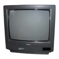
(1) Apply a signal to output terminals of the Main
Tuner on the Main PWB using the circuit shown
below. Connect 100Ω resistor between AGC ter-
minal, Pin 햲 and GND.
should be synchronized.
video output is 45dB or less.
Sound modulation condition:
Noise reduction encoder: ON
Stereo signal;
햲 R=0 (L only), 300Hz, 30% modulation
햳 R=0 (L only), 3kHz, 30% modulation
Monaural signal;
햴 Monaural, 400Hz, 100% modulation
(PRE-EN Off)
SAP signal;
햵 SAP, 300Hz, 30% modulation (see note)
(2) Connect AC voltmeter Vo to I401 pin .
Use the AC voltmeter of Matsushita model
VP-950C or equivalent.
Adjustment Procedure
(1) Select sound input 햴 then adjust the data “A04”
to Vo= 500mVrmsw10mVrms at I401 pin .
4-3-2 Stereo VCO adjustment
Adjustment Prepar
ation
(1) Same as items 4-3-1(1) and 4-3-1(2).
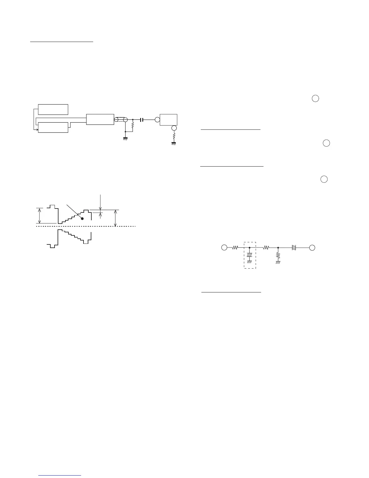
(2) Connect a frequency counter to I401 pin . Use
1:1 Probe.
(Probe standard Ri≥1MΩ, Ci≤15pF)
(3) Should be no signal at pin 햸 (I401).
(4) Connect capacitor (100µF/16v) as it is shown.
(5) Select adjustment code “A01.”
Adjustment Procedure
(1) Adjust the data “A01” to set 15.73±0.1KHz by 왗,왘
keys.
(2) Remove capacitor (100µF/16v)
 Loading...