9
DP45
(2) Apply covers to each color of R, G and B lenses.
And project a single color on the screen and
adjust in sequence. (The adjustment order of G,
R and B is only an example.)
(3) If the lens adjustment knob is turned clockwise
viewed from the front, the color Aberration
change as follows.
(NOTE 1)
Fixing Screw
(NOTE 2)
Fixing Wing Nut
TYPE 1 TYPE 2
Lens Assy
Lens Assy
Change of Color Aberration
Short focus Long focus
RED LENS Orange Scarlet
GREEN LENS Blue Red
BLUE LENS Purple Green
Color
Aberration
Cross-Hatch
Change of Color Aberration
Short focus Long focus
RED LENS Orange Scarlet
GREEN LENS Blue Red
BLUE LENS Purple Green
O
I
L1
L2
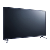
(4) In case of G lens. Set to the point where the
chromatic aberration switches from blue to red.
If the chromatic aberration appearing all over
the screen is not the same, observe the vertical
bright line and adjust lens focus as specified in
table below. When the red chromatic aberration
appearing at both sides of the bright line is not
equal, observe the side with larger chromatic
aberration when adjusting.
BACK TO ADJUSTMENTS
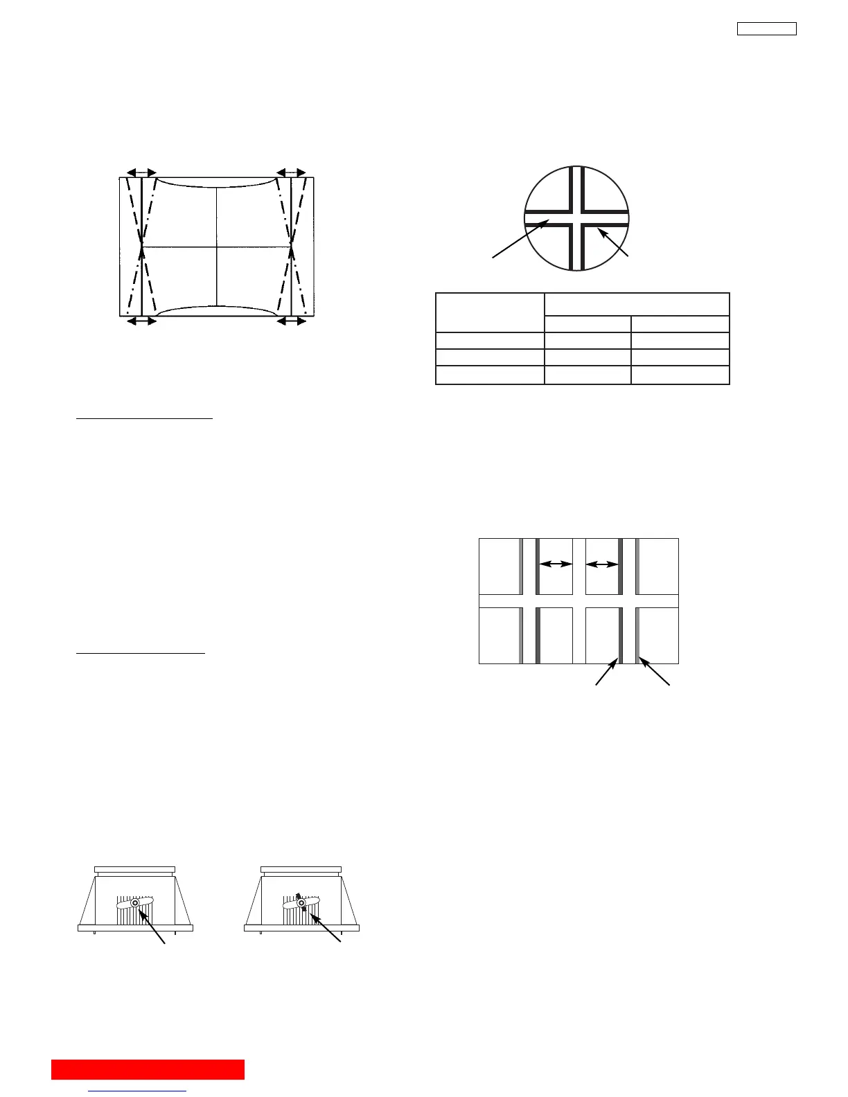
TRAPEZOID DISTORTION
(9) Choose “EW TRAP” (TRAPEZOID) item by
using
G, H keys.
(10)Adjust TRAPEZOID as follows using
F, E keys.
(11)After adjustment, press [EXIT] key on R/C and
SERVICE ONLY SW to exit from DCU
Crosshatch.
Vertical Screen frame line & edge of vertical DCU cross-
hatch line should be Prallel condition.
2.9 LENS FOCUS ADJUSTMENT
Adjustment preparation
(1) The orientation of PTV set is arbitrary, west,
east, north and south.
(2) Centering DY inclination should have been
adjusted.
(3) Static focus adjustment should have been
coarse adjusted.
(4) Drive VR location adjustment should have been
completed. (Red : 12 O’clock, Green : 1~2
O’clock).
(5) Receive the cross-hatch pattern signal.
(6) Refer to setup below.
CONTRAST : HALF of full scale.
BRIGHTNESS : minimum
Adjustment procedure
(1) Loosen the fixing screw or wing nut on the lens
cylinder so that the lens cylinder can be turned.
(Be careful not to loosen too much). After
completing steps (4), (5), (6) belo
w, tighten the
fixing screws or wing nuts for each lens with a
torque of 1.18N.m (12Kgf cm) ~ 1.67N.m (17Kgf
cm).
(Be careful the lens cylinder does not turn after
ha
ving tightened the scre
w or wing n
uts
. If it is
tightened too m
uch, lens may tilt or screw may
break.)