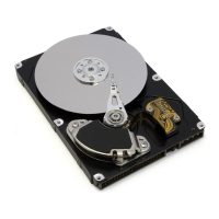
Do you have a question about the Hitachi 7K80 - Deskstar - Hard Drive and is the answer not in the manual?
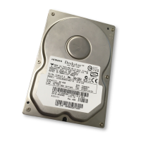
Introduces the Deskstar 7K80, 3.5-inch HDD with ATA interface.
Provides a list of abbreviations used in the document.
Details the formatted capacities and logical layout parameters for the drive models.
Provides mechanical positioning performance and buffer specifications.
Details the drive's organization, including formatting.
Defines command overhead and provides typical times for read and write commands.
Details mechanical positioning performance metrics like seek time.
Specifies power-on and ready states, including typical and maximum times.
Details disk-buffer and buffer-host transfer rates, including formulas for calculation.
Illustrates sequential and random access performance with formulas.
Describes various operating modes like Spin-up, Seek, Write, Read, Idle, Standby, and Sleep.
Shows the location of DC power and AT signal connectors on the drive.
Lists and defines the interface signals, including special definitions for Ultra DMA.
Provides detailed descriptions for individual signals like DD00-DD15, CS0-, CS1-, RESET-, DIOW, DIOR, INTRQ.
Details Ultra DMA cycle timings for initiating a read operation.
Illustrates Ultra DMA cycle timings when the host pauses a read operation.
Shows Ultra DMA cycle timings for host-terminating a read DMA.
Details Ultra DMA cycle timings for device-terminating a read DMA.
Explains Ultra DMA cycle timings for initiating a write operation.
Illustrates Ultra DMA cycle timings when the device pauses a write DMA.
Details Ultra DMA cycle timings for device-terminating a write DMA.
Shows Ultra DMA cycle timings for host-terminating a write DMA.
Provides recommendations for cable length and type for data transfer.
Details jumper settings for device configuration and drive operation.
Specifies operating and non-operating temperature and humidity limits.
Details input voltage specifications, supply rise time, and power connection guidelines.
Covers data integrity, cable noise interference, start/stop cycles, and data reliability.
Lists the drive's physical dimensions (height, width, length) and maximum weight.
Details vibration and shock test specifications for operating and non-operating conditions.
Presents sound power levels for the drive in different operating modes.
Lists the various labels affixed to the drive for identification purposes.
Covers UL/CSA approvals, German safety mark, flammability, safe handling, and environmental compliance.
States that the drive meets worldwide EMC requirements, including FCC and EEC directives.
Explains that drives are shipped in ESD protective bags and appropriate containers.
Describes the host interface of the HDS7280x0PLATy0 hard disk drive.
Lists deviations from referenced specifications, such as Check Power Mode and Hard Reset behavior.
Presents the I/O address map for Command Block and Control Block registers.
Describes the Alternate Status Register, similar to the Status Register but without interrupt implications.
Explains the Command Register, where the command code is written to initiate operations.
Explains the Data Register for transferring data blocks and configuration information.
Details the Device Control Register, including bits for HOB, SRST, and -IEN.
Details the Error Register, which contains status and diagnostic codes after command execution.
Explains the Sector Count Register for specifying the number of sectors for read/write operations.
Describes the Status Register, indicating the device's current status and command completion.
Outlines the device's response to Power On Reset, Hard Reset, and Soft Reset.
Details the default values of registers after power on, hard reset, or software reset.
Discusses how diagnostic tests and reset procedures are handled, including device presence detection.
Describes the logical CHS addressing mode, composed of cylinder, head, and sector numbers.
Explains the LBA addressing mode, mapping logical sectors linearly to physical locations.
Details the Sleep, Standby, Idle, and Active power modes.
Explains the standby timer for automatic entry into standby mode after inactivity.
Defines how power modes affect the physical interface, including BSY, RDY, and Media status.
Defines attributes as performance parameters used for device status analysis.
Explains attribute values representing device reliability, with higher values indicating lower degradation probability.
Describes attribute thresholds used for comparing against attribute values to detect degrading conditions.
Lists S.M.A.R.T. commands for accessing attribute data, thresholds, and logs.
Describes the off-line read scanning feature with reallocation for marginal sectors.
Details the error log feature, providing information on the last five reported errors.
Explains the self-test features initiated by S.M.A.R.T. commands for fault checking.
Details the security modes: Device Locked, Device Unlocked, and Device Frozen.
Describes security levels: High level and Maximum level security.
Explains the two types of passwords: Master Password and User Password.
Explains how a User Password is set and the subsequent lock mode entry.
Illustrates the device's operation from Power-On Reset after a user password is set.
Shows the device's response to commands when the Security Mode Feature Set is enabled.
Provides an example of preparing drives and setting up a protected area using LBA mode.
Lists security extensions like Set Max Set Password, Set Max Lock, and Set Max Unlock.
Details the subcommand to enable or disable the address offset mode.
Explains how Identify Device data indicates support for the Address Offset Feature.
Lists exceptions and commands rejected when in Address Offset mode.
Defines commands for streaming, emphasizing time-critical data transfers.
Specifies the Urgent bit for completing commands in the minimum possible time.
Details the Flush to Disk bit in Write Stream command for flushing data to media.
Specifies the Not Sequential bit for read stream commands.
Describes the Read Continuous bit for transferring data despite errors.
Explains the Write Continuous bit for completing requests without posting errors.
Specifies the Handle Streaming Error bit for continuing error recovery sequences.
Mentions the two error logs and one performance log accessed via Read Log Ext.
Lists PIO Data In commands, including Device Configuration Identity and Identify Device.
Lists PIO Data Out commands such as Device Configuration SET and Format Track.
Reports device power status and media availability for immediate access.
Specifies operating parameters for individual streams and allows adding/removing streams.
Discusses device configuration overlay features, including restore and freeze lock.
Enables the host to alter the device's microcode.
Performs internal diagnostic tests, storing results in the Error Register.
Causes the device to complete writing data from its cache to the disk media.
Similar to Flush Cache, commanding the device to write data from its cache to disk.
Formats a single logical track, initializing sectors to zero and potentially losing previous data.
Initializes all user data sectors and defect information, erasing previous data.
Requests configuration information transfer from the device to the host.
Causes the device to enter Idle mode and sets the auto power down timer.
Commands the device to enter Performance Idle mode immediately.
Allows the host to set sectors per track and heads per cylinder parameters.
Transfers data from the device's sector buffer to the host.
Reads sectors from disk and transfers data to host via DMA.
Reads multiple sectors via DMA, with interrupt generated per block.
Returns specified log sector contents to the host, interrupting for each DRQ block.
Defines the format of sectors comprising the Extended Comprehensive SMART error log.
Defines the format of sectors comprising the Extended SMART self-test log.
Defines the format of the Read Stream Error log, containing error entries.
Defines the format of the log returned by Read Log Ext for streaming performance.
Reads a sector and ECC bytes from disk media and transfers them to the host.
Reads multiple sectors from disk media and transfers them to the host with block-based interrupts.
Reads one or more sectors from disk media and transfers them to the host.
Reads from 1 to 65,536 sectors of data from disk media and transfers them to the host.
Allows the host to write data using DMA, with options for continuous read and error handling.
Reads sectors using PIO, with options for continuous read and error handling.
Verifies one or more sectors on the device without transferring data to the host.
Verifies sectors without data transfer, differing from Read Sector(s) command.
Moves read/write heads to cylinder 0.
Disables the security mode feature (device lock function) by transferring password data.
Must be issued before Security Erase Unit to enable device erasing and unlocking.
Initializes all user data sectors and disables the device lock function, erasing all data.
Allows the device to enter frozen mode immediately, rejecting commands that update security features.
Enables security mode and sets master or user password, locking the device on the next reset.
Unlocks the password and causes the device to enter device unlock mode.
Initiates a seek to a designated track and selects the designated head.
Establishes parameters affecting features like write cache and power management.
Overwrites the maximum drive address, rejecting accesses beyond the set address.
Overwrites the maximum HDD address, with different behavior for addresses above/below 268,435,455.
Enables Read/Write Multiple commands and establishes the block size for them.
Causes the device to enter Sleep Mode, spinning down the drive and deactivating the interface.
Provides access to Attribute Values, Thresholds, and other S.M.A.R.T. subcommands.
Defines the 512 bytes making up the Attribute Value information.
Shows register values for specific error conditions encountered by the device.
Causes the device to enter Standby Mode immediately and sets the auto power down timer.
Commands the device to enter Standby Mode immediately, without affecting the auto power down timer.
Transfers a sector of data from the host to the sector buffer of the device.
Transfers sectors from host to device via DMA, writing data to disk media.
Transfers sectors via DMA, with interrupts generated per block.
Writes specified 512-byte data sectors to a log, interrupting for each DRQ block.
Transfers data and ECC bytes of a sector from host to device.
Transfers one or more sectors from host to device, identical to Write Sectors except for interrupts.
Transfers multiple sectors from host to device, with block interrupts defined by Set Multiple command.
Transfers one or more sectors from host to device, writing data to disk media.
Transfers sectors from host to device, writing data to disk media.
Allows the host to write data using DMA, with options for continuous read and error handling.
Writes sectors using PIO, with options for continuous write and error handling.
