--------------------------------------------------------HMCS47C,HMCS47CL
LSI
Internal
Clock
4
<Pl
<P2
SED, REO, [
SEDD,
REDO
Instruction
TO
[
Instruc·
tion
/
o I ne
nstructlon
C I
yce
'\
JL
J--"l
h
r---L
r-----,
r---t
-
On
SetlReset
-
Instruction
On
(LSI
pin)
On
Test
Instruction
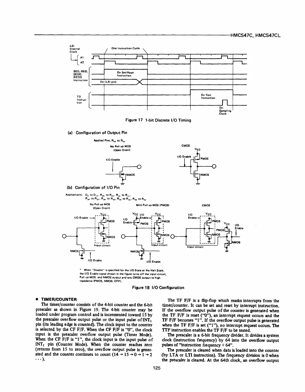
Figure
17
1-bit Discrete
I/O
Timing
(a)
Configuration
of
Output
Pin
Applied Pins;
R.
o
to
R
..
No Pull up MOS
(Open Drain)
I/O
Enable
~F
(b) Configuration
of
I/O
Pin
Applied
pins;
Do
to
0.,.
Roo
to
R
O
)'
RIO
to
Ru.
R
10
to
R2l'
R)O
to
Au.
R.
o
to
R,n.
Rso
to
RS)
No Pull
UP
MOS
(Opon
Drain)
I/O
Enable
-f-
-'!.~CC-l
I
PMOS
r-
__
.........
1
....
!
, ,
, ,
, I
:
N,MOS
, ,
L
______
J
Input
circuit
With
Pull up
MOS
(PMOS)
~~able~cc
~~able_r_~-~C_C-~MOS
1
PMOS'
,
---+:
..
!
, ,
:
NjMOS
L
_____
J
Input
circuit
•
When
"Disable"
is
specified
for
the
I/O
State
at
the
Halt
State,
the 1/0 Enable signal shown in the figure turns
off
the
input
circuit,
Pull up MOS and NMOS
output
and
sets
CMOS
output
to
high
inpedance
(PMOS, NMOS; OFF).
CMOS
"TI~
Y~N_
-
CMOS
Figure 18
I/O
Configuration
...II.
t""L-
f---
On
Samplin
Clock
I/O
U
ble
~NMOS
• TIMER/COUNTER
The
TF
F/F
is
a flip-flop which masks interrupts from the
timer/counter.
It
can be set and reset by interrupt instruction.
If
the overflow output pulse
of
the counter
is
generated when
the TF F
/F
is
reset
("0"),
an interrupt request occurs and the
TF
F/F becomes
"1".
If
the overflow output pulse
is
generated
when the
TF
F
/F
is
set ("1
"),
no interrupt request occurs. The
TIF
instruction enables the
TF
F
/F
to
be
tested.
The timer/counter consists
of
the 4-bit counter and the 6-bit
pre scaler
as
shown in Figure
19.
The 4-bit counter may be
loaded under program control and
is
incremented toward
15
by
the prescaler overflow output pulse
or
the input pulse
ofINT
1
pin (its leading edge
is
counted). The clock input to the counter
is
selected by the CF F/F.
When
the
CF
F/F
is
"0",
the clock
input
is
the prescaler overflow output pulse (Timer Mode).
When
the CF F
/F
is
"1",
the clock input
is
the input pulse 0 f
INT
~
pin (Counter Mode).
When
the counter reaches zero
(returns from
15
to zero), the overflow output pulse
is
gener-
ated and the counter continues to count (14
-+
15
-+
0
-+
1
-+
2
..
, ).
125
The
prescaler
is
a 6-bit frequency divider.
It
divides a system
clock (instruction frequency) by 64 into the overflow output
pulses
of
''instruction frequency + 64".
The prescaler
is
cleared when data
is
loaded into the counter
(by LTA or LTI instruction). The frequency division
is
0 when
the prescaler
is cleared. At the 64th clock, an overflow output
 Loading...

