---------------------------------
LCD-IV
ing an external interrupt to the LCD-IV.
Refer
to
INTERRUPTS for additional infonnation.
• V I , V 2
and
V 3
Power for liquid crystal display
are
supplied to the LCD-IV
usingthesepins(Vcc~VI
~V2
~V3
~GND).
•
Roo
to
R03
These 4 lines are a 4-bit input channel.
Refer
to
INPUT/OUTPUT for additional infonnation.
• RIo
to
R13,
R20
to
R23
These 8 lines are arranged into two 4-bit Input/Output
common channels.
The 4-bit register
is
attached
to
this channel. This channel
is
directly addressed by the operand
of
an instruction. I/O
configuration
of
each pin can be specified among Open Drain
and
CMOS
using a mask option.
Refer to
INPUT/OUTPUT for additional infonnation.
•
R30
to
R33
These 4 lines are a 4-bit output channel.
4-bit register
is
attached to this channel. This channel
is
directly addressed by the operand
of
an instruction. I/O con-
figuration
of
each pin can be specified among Open Drain and
CMOS
using a mask option.
Refer to
INPUT/OUTPUT for additional infonnation.
•
Do
to
013
These are
14
discrete signals which can
be
configured
as
Input/Output lines.
Refer
to
INPUT/OUTPUT for additional information.
•
014/XO,0Is/XI
D
I4
/XO and DIS/XI require a mask option
in
the following
3 types.
• Discrete I/O (common tenninal)
• Crystal circuit connecting terminals (with internal halt)
• Crystal circuit connecting terminals (no internal halt)
Refer to
INPUT/OUTPUT for additional infonnation.
•
COMI
to
COM.
These pins are common tenninals for liquid crystal display.
Refer
to
LIQUID CRYSTAL DISPLAY for additional in-
fonnation.
•
SEGI
to
SEG32
These pins are segment tenninals for liquid crystal display.
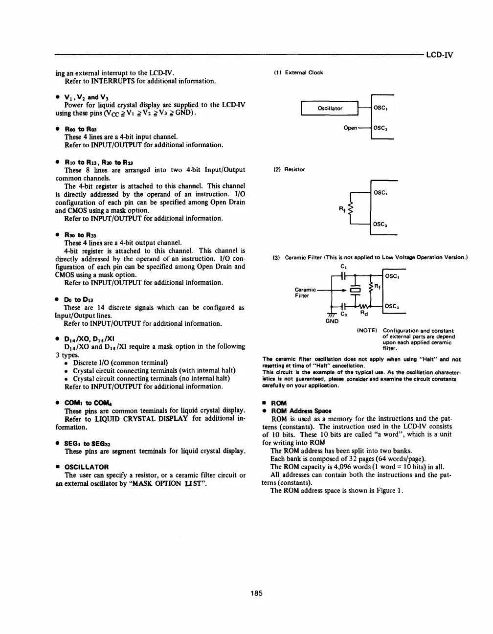
• OSCILLATOR
The user can specify a resistor, or a ceramic filter circuit
or
an external oscillator by "MASK OPTION U ST".
(1) External Clock
Oscillator
OSC.
Open
(2)
Resistor
(3) Ceramic Filter (This
is
not
applied
to
Low Voltage Operation Version.!
C.
-f
OSC.
Rf
~~~~iC
-~""""\M,_~
OSC
2
C
2
Ad
GND
(NOTE) Configuration and
constant
of external parts are depend
upon each applied ceramic
filter.
The ceramic filter oscillation does
not
apply when using
"Halt"
and
not
resetting
at
time
of
"Halt"
cancellation.
This circuit
is
the
example
of
the
typical use.
As
the
oscillation character-
istics
is
not
guaranteed, please consider end examine
the
circuit constants
carefully
on
your
application.
• ROM
• ROM
Address Space
ROM
is
used
as
a memory for the instructions and the pat-
terns (constants). The instruction used in the
LCD-IV consists
of
10 bits. These 10 bits are called
"a
word", which
is
a unit
for writing into
ROM
The
ROM
address has been split into two banks.
Each bank
is
composed
of
32
pages (64 words/page).
The
ROM
capacity
is
4,096 words
(1
word = 1 0 bits) in all.
All
addresses can contain both the instructions and the pat-
terns (constants).
The
ROM
address space
is
shown
in
Figure 1.
185


 To Next Page
 Loading...


