---------------------------------
LCD-IV
I/E reset
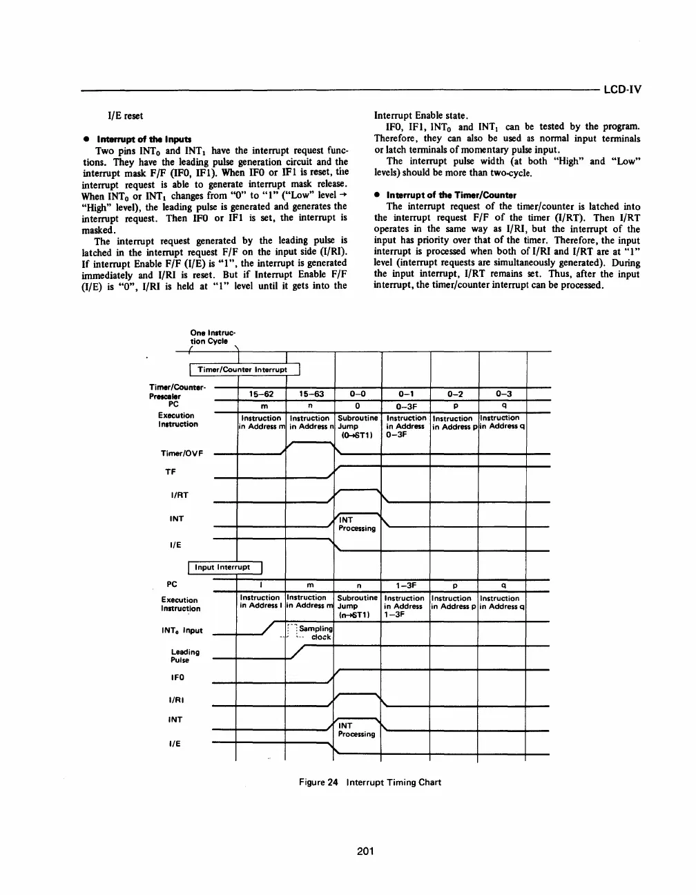
• Interrupt
of
the
Inputs
Two pins
INTo
and INTI
have
the interrupt request func-
tions. They
have
the leading pulse generation circuit and the
interrupt mask F/F
(lFO,
IFI).
When
IFO
or IFI is reset, the
interrupt request
is
able
to generate interrupt
mask
release.
When
INTo
or
INTI
changes from
"0"
to
")"
("Low"
level
-+
"High" level), the leading pulse
is
generated and generates the
interrupt request. Then
IFO
or
1Ft
is
set, the interrupt
is
masked.
The interrupt request generated by the leading pulse
is
latched
in
the interrupt request F/F on the input side (I/RI).
If
interrupt Enable F/F (I/E)
is
"I",
the interrupt
is
generated
immediately and I/RI
is
reset. But
if
Interrupt Enable F/F
(I/E)
is
"0",
I/RI
is
held at
")"
level
until it gets into the
One
Inltruc-
tion
Cycle
/
'\
I
TimerlCounter
Interrupt
Counter-Timerl
Prncale
P
r
15-62
C
m
I
15-63
n
0-0
0
Interrupt Enable state.
IFO,
IF),
INTo
and
INTI
can
be
tested by the program.
Therefore, they
can
also
be
used
as
normal input terminals
or latch terminals
of
momentary
pulse
input.
The interrupt pulse width (at both
"High" and "Low"
levels) should
be
more than two-cycle.
• Interrupt
of
the Timer/Counter
The interrupt request
of
the timer/counter
is
latched into
the interrupt request F/F
of
the timer (I/RT). Then I/RT
operates
in
the
same
way
as
I/RI, but the interrupt
of
the
input
has
priority over that
of
the timer. Therefore, the input
interrupt
is
processed when both
of
I/RI and I/RT are at
"I"
level
(interrupt requests are simultaneously generated). During
the input interrupt, I/RT remains set. Thus, after the input
interrupt, the timer/counter interrupt can
be
processed.
0-1
0-2
0-3
0-3F
p
q
ution
Exec
Inltr
uction
Instruction Instruction Subroutine Instruction
Instruction
Instruction
in Address m
Time
r/OVF
TF
IRT
IN
T
II
E
I
Input
Interrupt
1
PC
Exe
I
nit
cut ion
ruction
INT
o
Input
eading
ulse
L
P
FO
II
RI
IN
T
II
E
I
Instruction
in Address I
--
in
Address n
Jump
in
Address
in
Address p
in Address q
(Q--.sT11
0-3F
r\.
~
INT
r\.
Processing
m
n
1-3F
p
q
Instruction
Subroutine
Instruction
Instruction Instruction
in
Address m
Jump
in
Address in Address p
in Address q
(~T11
1-3F
r--:
Sampling
.
~--
clock
I\.
INT
Processing
Figure 24
Interrupt
Timing Chart
201


 To Next Page
 Loading...


