--------------------------------------------------------------------LCD-IV
I
Becomes halt
state
after executing RED
instruction and
the
halt
is
maintained
.--
__
L
V_I
_....,15
until a prescaler overflow signal
is
issued.
L-~R~E~D
__
r_------~--~.
LVI
0
f-L
TO
BR
.-4
The
LCD-IV returns from halt
state
by
a pre-
scaler overflow signal and operation restarts
from
LVI
instruction. With this program,
unless
the
Do
terminal
is
set
to
"0",
internal
halt
state
Occurs repeatedly.
Figure
33
Program example
in
the Internal Halt Mode
Program~
V---------
n
+1
~
Counter
~
___
.....
"---
__________
"-n+2--A--.-
ROM --::-v n + 1
Address
~
______
___
_________
-J
x
n+2
X~
_______________
_
ROM
-::J\
~r
\'-
____
n_+_1
___
--JX'-
____
......
~
--\-----Halt
State~
Halt Signal - - - - - 16 Instructions
Prescaler
Overflow------------·
----------------
Signal
Figure
34
Internal Halt Timing Chart
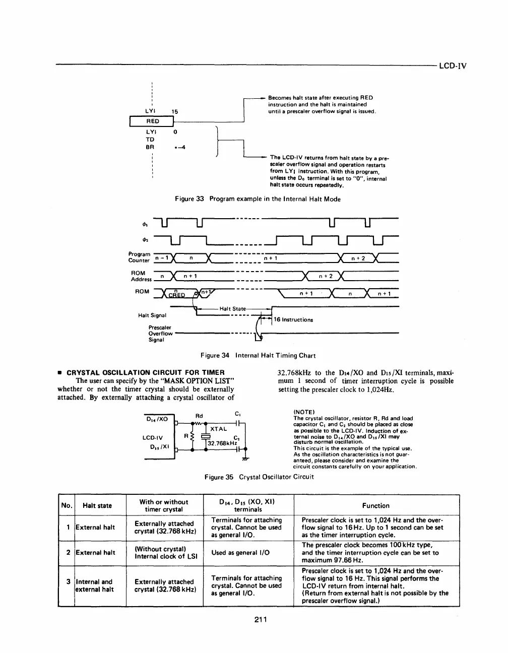
• CRYSTAL OSCILLATION CIRCUIT FOR TIMER
The user can specify
by
the "MASK OPTION LIST"
whether
or
not
the timer crystal should be externally
attached. By externally attaching a crystal oscillator
of
32.768kHz to the DI4/XO and DIS/XI terminals, maxi·
mum
1 second
of
timer interruption cycle is possible
setting the prescaler clock
to
1,024Hz.
No.
Halt state
1 External halt
2
External
halt
3
I nternal and
external halt
D
I4
/XO
LCD-IV
D15/
XI
Rd
R
With
or
without
timer crystal
Externally
attached
crystal (32.768 kHz)
(Without crystal)
Internal clock
of
LSI
Externally attached
crystal (32.768 kHz)
c.
(NOTE)
The crystal oscillator, resistor R,
Rd
and load
capacitor C
I
and C
a
should
be
placed as close
as
possible
to
the
LCD-IV. Induction
of
ex-
ternal noise
to
D
14
/XO and D15/XI may
disturb normal oscillation.
This circuit
is
the
example of
the
typical use.
As
the
oscillation characteristics
is
not
guar-
anteed,
please consider and examine
the
circuit constants carefully on
your
application.
Figure 35 Crystal Oscillator Circuit
0
14
,0
15
(XO, XI)
Function
terminals
Terminals for attaching
Prescaler
clock
is
set
to
1,024
Hz
and
the
over-
crystal. Cannot be used
flow signal
to
16 Hz. Up
to
1 second can be set
as
general I/O.
as
the
timer interruption cycle.
The prescaler
clock becomes
100
kHz type,
Used as general I/O and
the
timer interruption cycle can be set
to
maximum
97.66
Hz.
Prescaler
clock
is
set
to
1,024
Hz
and
the
over·
Terminals for attaching
flow signal
to
16 Hz. This signal performs
the
crystal. Cannot be used
LCO·IV return from internal halt.
as general I/O. (Return from external halt
is
not
possible by
the
prescaler overflow signaL)
211


 To Next Page
 Loading...


