HMCS404C--------------------------------------------------------------
Instruction
Cycles
Instruction
execution
Interrupt
accepted
2
Stacking,
Reset
of
lIE
3
Stacking,
Vector address
is
generated
4
5
JMPL instruction exacution on
the
vector address
6
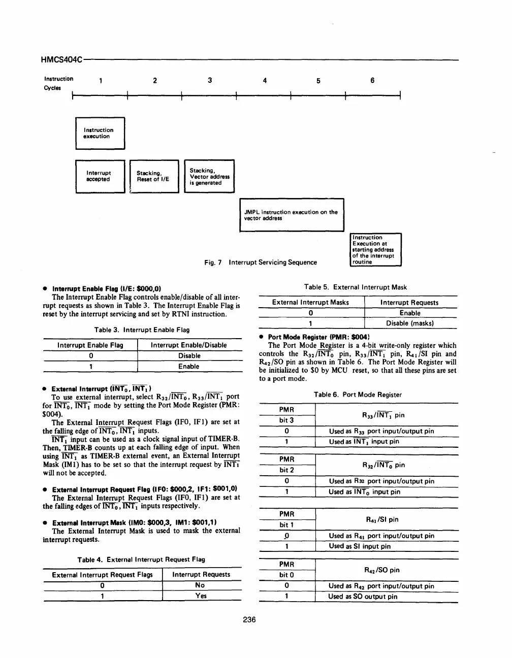
Fig. 7
Interrupt
Servicing
Sequence
Instruction
Execution at
starting address
of the interrupt
routine
• Interrupt Enable
Flag
(lIE: $000,0)
The Interrupt Enable Flag controls enable/disable
of
all inter-
rupt requests
as
shown
in
Table 3. The Interrupt Enable Flag
is
reset by the interrupt servicing and set by RTNI instruction.
Table
3.
Interrupt
Enable Flag
Interrupt
Enable Flag
Interrupt
Enable/Disable
o Disable
Enable
• External Interrupt (INTo, INTI)
To
use
external interrupt, select R
32
/INT
o
, R33/INT I port
for INTo,
INTI mode by setting the Port Mode Register (PMR:
$004).
The External Interrupt Request Flags (lFO,
IFI)
are set at
the falling edge
of
INTo, INT I inputs.
INT
I input can be used
as
a clock signal input
of
TIMER-B.
Then,
TIMER-B
counts up
at
each falling edge
of
input. When
using
INT
I
as
TIMER-B external event,
an
External Interrupt
Mask
(IMI) has
to
be set so that the interrupt request by INTI
will
not
be
accepted.
• External Interrupt Request Flag (lFO: $000,2, IF1: $001,0)
The External Interrupt Request Flags (IFO,
IFI)
are set at
the falling edges
of
INTo,
~
inputs respectively.
• External Interrupt
Mask
(lMO:
$000,3,
IM1:
$001,1)
The External Interrupt
Mask
is
used
to
mask the external
interrupt requests.
Table
4.
External
Interrupt
Request
Flag
External
Interrupt
Request
Flags
Interrupt
Requests
o
No
Yes
236
Table 5. External
Interrupt
Mask
External
Interrupt
Masks
Interrupt
Requests
o
Enable
Disable
(masks)
• Port Mode Register
(PMR:
$O04)
The Port Mode Register
is
a 4-bit write-only register which
controls the R32/INTo pin, R33/INTI pin,
~dSI
pin and
~2
ISO pin
as
shown in Table 6. The Port Mode Register will
be initialized to
$0 by MeU reset,
so
that
all
these pins are set
to
a port mode.
Table
6.
Port
Mode Register
PMR
R33/INTI pin
bit
3
0 Used as
R33
port
input/output
pin
Used as
I NT I
input
pin
PMR
R32/INTo
pin
bit
2
0 Used as
R32
port
input/output
pin
Used as
I NT 0
input
pin
PMR
R
41
/SI pin
bit
1
_0
Used as
R41
port
input/output
pin
Used as
SI
input
pin
PMR
bit
0
R42/S0
pin
0
Used as
R42
port
input/output
pin
Used as
SO
output
pin


 To Next Page
 Loading...


