----------------------------------------------------------------HMCS404C
t-"--'-'-'--~
TCA(8bit)
TIMER COUNTER A
INTERRUPT
REQUEST
FLAG
OF
TIMER-A
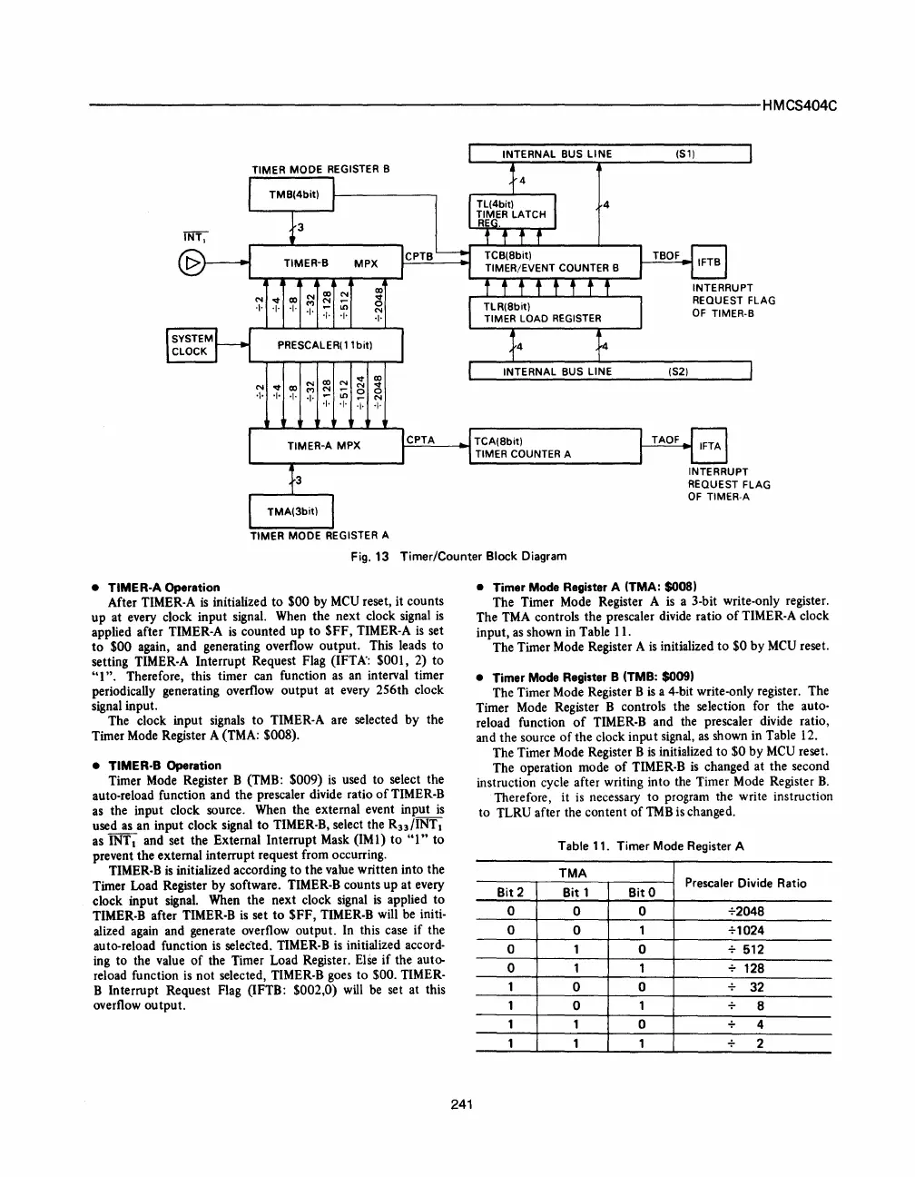
Fig.13
Timer/Counter Block Diagram
• TIMER·A Operation
After TIMER·A
is
initialized
to
$00
by
MeV
reset,
it
counts
up
at every clock
input
signal. When the
next
clock signal
is
applied after TIMER·A
is
counted
up
to
$FF,
TIMER·A
is
set
to
$00
again, and generating overflow
output.
This leads
to
setting TIMER·A
Interrupt
Request Flag (IFTA': $001, 2)
to
"1".
Therefore, this timer can function as an interval timer
periodically generating overflow
output
at every
256th
clock
signal input.
The clock input signals
to
TIMER·A are selected
by
the
Timer Mode Register A (TMA: $008).
• TIMER·B Operation
Timer Mode Register B (TMB:
$009)
is
used
to
select the
auto·reload function
and
the
prescaler divide ratio
of
TIMER·B
as the input clock source. When the external event input
is
used as
an
input clock signal
to
TIMER·B, select the
R33
lINT
I
as INT I and set the External
Interrupt
Mask
(1M
1)
to
"1"
to
prevent
the
external interrupt request from occurring.
TIMER·B
is
initialized according
to
the
value
written
into
the
Timer Load Register
by
software. TIMER·B counts
up
at
every
clock
input
signal. When
the
next
clock signal
is
applied
to
TIMER·B after TIMER·B
is
set
to
$FF,
TIMER·B will be initio
alized again and generate overflow
output.
In this case
if
the
auto·reload function is selecled. TIMER·B is initialized accord·
ing to the value
of
the Timer Load Register. Else
if
the auto-
reload function is
not
selected, TIMER·B goes
to
$00. TIMER·
B
Interrupt
Request Flag (IFTB: $002,0) will be set at this
overflow
output.
241
• Timer Mode Register A (TMA: S008)
The Timer Mode Register A is a 3·bit write·only register.
The TMA controls the prescaler divide ratio
of
TIMER·A clock
input, as shown in Table 11.
The Timer Mode Register A
is
initialized
to
$0
by
MeV
reset.
• Timer Mode Register B (TMB:
SOO9)
The Timer Mode Register B
is
a 4·bit write·only register. The
Timer Mode Register B controls the selection for the auto·
reload function
of
TIMER·B and the prescaler divide ratio,
and the source
of
the
clock inpu t signal, as shown in Table 12.
The Timer Mode Register B
is
initialized
to
$0
by
MeV
reset .
The
operation mode
of
TIMER·B
is
changed
at
the
second
instruction cycle after writing into the Timer Mode Register
B.
Therefore,
it
is necessary
to
program the write instruction
to
TLRV after the
content
of
TMB is changed.
Table 11. Timer Mode Register A
TMA
Bit
2
Bit
1
BitO
Prescaler
Divide Ratio
0
0 0
+2048
0
0
1 +1024
0
1 0 + 512
0 1 1
128
1
0 0
32
1
0 1
8
1 1
0 4
1 1 1 2


 To Next Page
 Loading...


