--------------------------------------------------------------HD614P080S
•
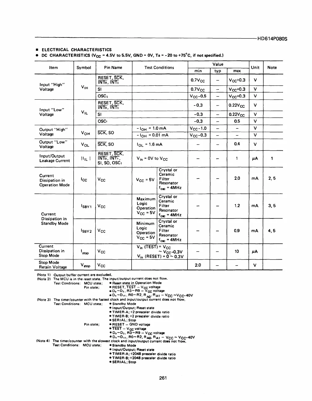
ELECTRICAL
CHARACTERISTICS
•
DC
CHARACTERISTICS
(Vee
=
4.5V
to
5.5V,
GND
=
OV,
Ta
=
-20
to
+75°C,
if
not
specified.)
Item
Symbol
Pin
Name
Test
Conditions
RESET,SCI<,
INTo,lNTI
Input
"High"
VIH
Voltage
SI
OSCI
RESET,
SCK,
INTo,lNTI
Input
"Low"
V
IL
Voltage
SI
OSC,
Output
"High"
-IOH
=
1.0mA
Voltage
VOH
SCK,
SO
-
IOH
= 0.01
mA
Output
"Low"
VOL
SCK,
SO
IOL
=
1.6
mA
Voltage
Input/Output
RESET,
SCK,
IIIL I
INTo,lNT"
Vin =
OV
to
Vce
Leakage
Current
SI,
SO,
OSCI
Crystal
or
Current
Ceramic
Dissipation
in
ICC
VCC
Vce
=
5V
Filter
Operation
Mode
Resonator
fo£
=
4MHz
Maximum
Crystal
or
Logic
Ceramic
IS
B
Y1
Vce
Filter
Operation
Resonator
Current
Vec
=
5V
fo£
=
4MHz
Dissipation
in
Crystal
or
Standby
Mode
Minimum
Ceramic
ISBY2
Vec
Logic
Filter
Operation
Vee
=
5V
Resonator
fo£
=
4MHz
Current
Vin
(TEST)
=
Vee
Dissipation
in
I stop
Vce
'"
Vec-
0
.
3V
Stop
Mode
V
in
(RESET)
= 0
'"
0.3V
Stop
Mode
V
stop
Vcc
Retain
Voltage
(Note
1)
(Note
2)
Output buffer current are excluded.
The
MCU
is
in
the reset state. The input/output current does not flow.
Test Conditions:
MCU
state; • Reset state
in
Operation
Mode
Pin
state; • RESET, TEST -
Vee
voltage
•
Do
-0"
R3
-
R9
-
Vee
voltage
min
0.
7V
ee
0.
7V
ee
Vee-
O
.
S
-0.3
-0.3
-0.3
Vee-
1
.
O
Vee-
0
.
3
-
-
-
-
-
-
2.0
(Note
3)
• O.
-0",
RO-
R2, R
AIJ'
RA1
-
Vec
-Vee-40V
The timer/counter with the fastest clock and input/output current does not flow.
(Note 4)
Test Conditions: MeU state;
• Standby
Mode
• Input/Output; Reset state
• TIMER-A;
+2
prescaler divide ratio
• TlMER-B;
+2
prescaler divide ratio
• SERIAL; Stop
Pin
state; • RESET - GNO voltage
• TEST
-
Vee
voltage
•
0.-0"
R3-R9
-
Vee
voltage
-
O.
-0",
RO-
R2,
RAIJ,
RA1
-
Vee
-
Vee-40V
The timer/counter with the slowest clock and input/output current does not
flow_
Test Conditions:
MCU
state;
-Standby
Mode
• Input/Output; Reset state
- TIMER-A; +2048 prescaler divide ratio
- TIMER-S; +2048 prescaler divide ratio
• SERIAL; Stop
261
Value
typ
-
-
-
-
-
-
-
-
-
-
-
-
-
-
-
Unit
Note
max
Vce+
0
.
3
V
Vee+
0
.
3
V
Vcc+
0
.
3
V
0.
22V
ce
V
0.
22V
ce
V
0.5
V
-
V
-
V
0.4
V
1
IJA
1
2.0
mA
2,5
1.2
mA
3,5
0.9
mA
4,5
10
IJA
-
V


 To Next Page
 Loading...