HD614P080S---------------------------------------------------------------
bit
3
bit
2
bit
1
bit
0
IMO
IFO
RSP
I/E
(1M
of
iNTo)
(IF
of
INTo)
(Reset
SP
Bit)
(Interrupt
Enable Flag)
o
$000
IMTA IFTA IM1
IF1
(1M
of
TIMER-A)
(IF
of
TIMER-A)
(1M
of
INT
1
)
(IF
of
INT
1
)
$001
Not
Used
Not
Used
IMTB IFTB
(1M
of
TIMER-B)
(IF
of
TIMER-B)
2
$002
Not
Used
Not
Used
IMS
IFS
(1M
of
SERIAL)
(IF
of
SERIAL)
3
$003
IF Interrupt Request
Flag
1M
Interrupt
Mask
lIE Interrupt Enable
Flag
SP
Stack Pointer
(Note)
Each
bit
in Interrupt Control Bits
Area
is
set
by SEM/SEMD instruction,
is
reset
by REM/REMD instruction
and
is
tested
by
TM/TMD
instruction.
It
is
not affected by other instructions. Furthermore, Interrupt
Request
Flag
is
not affected by SEM/SEMD instruction.
The content
of
Status
becomes
invarid when "RSP"
bit
and
"Not
Used"
bit
is
tested.
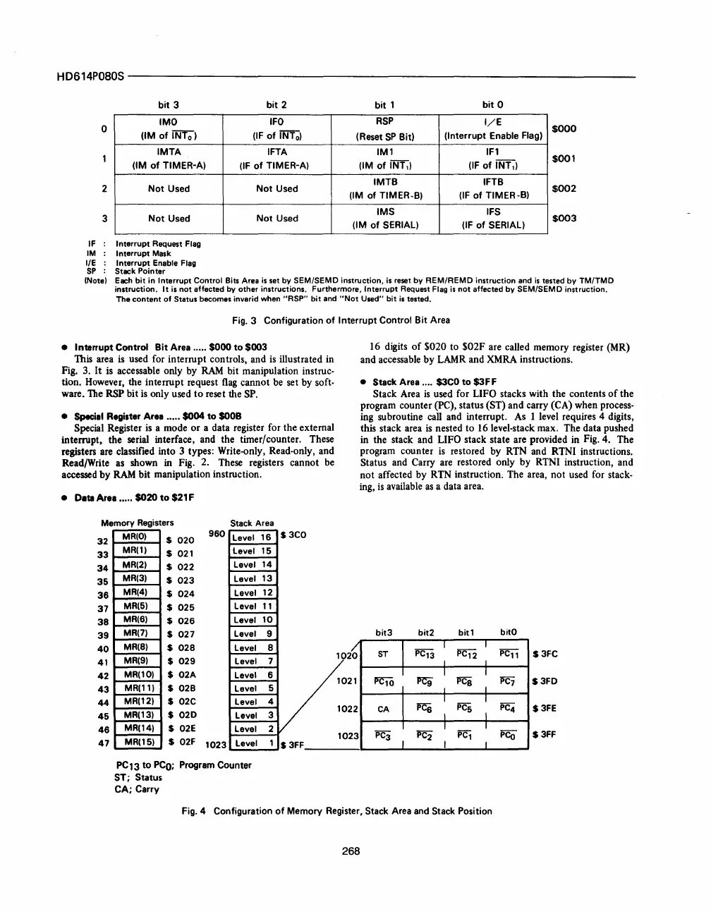
Fig.
3 Configuration
of
Interrupt Control
Bit
Area
• Interrupt Control
Bit
Area ..... $000
to
$003
This area
is
used for interrupt controls, and
is
illustrated in
Fig. 3.
It
is accessable only by
RAM
bit manipulation instruc-
tion. However, the interrupt request
flag
cannot be set by soft·
ware. The RSP
bitis
only used
to
reset the
SP.
•
Speci.1
Register Area .....
$004
to
$OOB
Special Register
is
a mode
or
a data register for the external
interrupt, the serial interface, and the timer/counter. These
registers are classified into 3 types: Write-only, Read-only, and
Read/Write as shown in Fig. 2. These registers cannot be
accessed
by
RAM
bit manipulation instruction.
• Date Are
......
$020
to
$21 F
Memory
Registers
Stack
Area
MR(O)
$
020
960
Level
16
S3CO
MR(l)
$
021
Level
15
MR(2)
$
022
Level
14
MR(3)
$
023
Level
13
MR(4)
$
024
Level
12
MR(5)
$
025
Level
11
MR(6)
$
026
Level
10
MR(7)
$
027
Level
9
MR(8)
$
028
Level
8
16 digits
of
$020 to $02F are called memory register (MR)
and accessable by LAMR and XMRA instructions.
• Stack Area .... $lCO
to
$lFF
Stack Area
is
used for LIFO stacks with the contents
of
the
program counter (PC), status (ST) and carry (CA) when process-
ing subroutine call and interrupt. As 1 level requires 4 digits,
this stack area
is
nested
to
16 level-stack max. The data pushed
in the stack and LIFO stack state are provided in Fig. 4. The
program counter
is
restored by RTN and RTNI instructions.
Status and Carry are restored only by RTNI instruction, and
not
affected by RTN instruction. The area,
not
used for stack-
ing,
is
available
as
a data area.
bit3
bit2
bitl
bitO
32
33
34
35
36
37
38
39
40
41
42
43
44
45
46
47
MR(9)
MR(10)
MR(ll)
MR(12)
MR(13)
MR(14)
$
029
$
02A
$
028
$
02C
$
020
$
02E
Level
7V
Level
6 1
Level
5
Level
4
Level
3 1
Level
2
1
023
PC11
S3FC
PC10
PC7
S3FD
CA
PC4
$3FE
PC3 PC2
PC1
PCo
S3FF
MR(15)
$
02F
1023
Level
PC13
to
PCO;
Program Counter
ST; Status
CA;
Carry
1 S 3FF
Fig.4
Configuration
of
Memory Register, Stack Area
and
Stack Position
268


 To Next Page
 Loading...



