HMCS404AC--------------------------------------------------------------------------
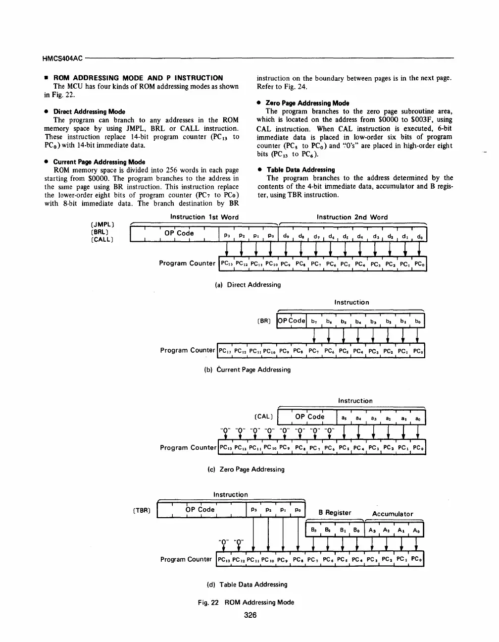
• ROM ADDRESSING MODE AND P INSTRUCTION
The
MCU
has four kinds
of
ROM
addressing modes as shown
in Fig. 22.
• Direct Addressing Mode
The program can branch to any addresses in the
ROM
memory space by using JMPL, BRL or CALL instruction.
These instruction replace 14-bit program counter
(PC
n
to
PC
o
)
with 14-bit immediate data.
• Current Page Addressing Mode
ROM
memory space
is
divided into 256 words
in
each page
starting from
$0000. The program branches
to
the address in
the
same
page using BR instruction. This instruction replace
the lower-order eight bits
of
program counter
(PC7
to PCo)
with 8-bit immediate data. The branch destination by BR
(JMPL)
(BRL)
(CALL)
Instruction
1 st
Word
instruction on the boundary between pages is in the next page.
Refer
to
Fig. 24.
• Zero Page Addressing Mode
The program branches
to
the zero page subroutine area,
which
is
located
on
the address from $0000
to
$003F, using
CAL instruction. When CAL instruction
is
executed, 6-bit
immediate data
is
placed in low-order six bits
of
program
counter
(PC
s
to
PC
o
)
and
'.'O's"
are placed in high-order eight
bits
(pC
13
to
PC
6
).
• Table Data Addressing
The program branches to the address determined by the
contents
of
the 4-bit immediate data, accumulator and B
regis-
ter, using TBR instruction.
Instruction
2nd
Word
(a)
Direct Addressing
(TBR)
Instruction
(BR)
Program Counter
PC"
PC
••
PC"
PC.
o
PC.
PC
a
(b) Current
Page
Addressing
Instruction
(c)
Zero
Page
Addressing
Instruction
Program Counter
~~--~~--~~~~~~~~~--~~--~~
(d) Table Data Addressing
Fig.22
ROM Addressing Mode
326



 To Next Page