--------------------------------------------------------------------------HMCS404CL
•
AC
CHARACTERISTICS
(Vee=2.7V
to
6V,
GND
=
OV,
Vdisp =
Vee-40V
to
Vee,
Ta
=
-20
to
+75°C,
if
not
specified.)
Value
Item
Symbol
Pin
Name
Test
Conditions
Unit
Note
min
typ
max
Oscillation
Frequency
fosc
aSCI,
aSC2
0.4
2
2.25
MHz
Instruction
Cycle
Time
tcyC
3.55
4
20
p.s
Oscillator
Stabilization
Time
tRC
aSCI,
aSC2
- -
60
ms
1
External
Clock
"High"
tCPH
ascI
205
-
-
ns 2
Level
Width
External
Clock
"Low"
tCPL
ascI
205
-
2
Level Width
-
ns
External
Clock Rise
Time
tCPr
ascI
-
-
20
ns 2
External
Clock
Fall
Time
tCPf
ascI
-
-
20
ns 2
INTo
"High"
Level Width
tlOH
INTo
2 - -
tcyc
3
INTo
"Low"
Level Width
tlOL
INTo 2 -
-
tcyc
3
INTI
"High"
Level Width
tllH
INTI
2 - -
tcyc
3
INTI
"Low"
Level Width
til
L
INTI
2 - -
tCYC
3
RESET
"High"
Level Width
tRSTH
RESET
2 -
-
tCyc
4
Input
Capacitance
Cin
all pins
f
= 1 MHz
- - 15
pF
V
in
= 0 V
RESET
Fall
Time
tRSTf
-
-
15
ms 4
(Note
1)
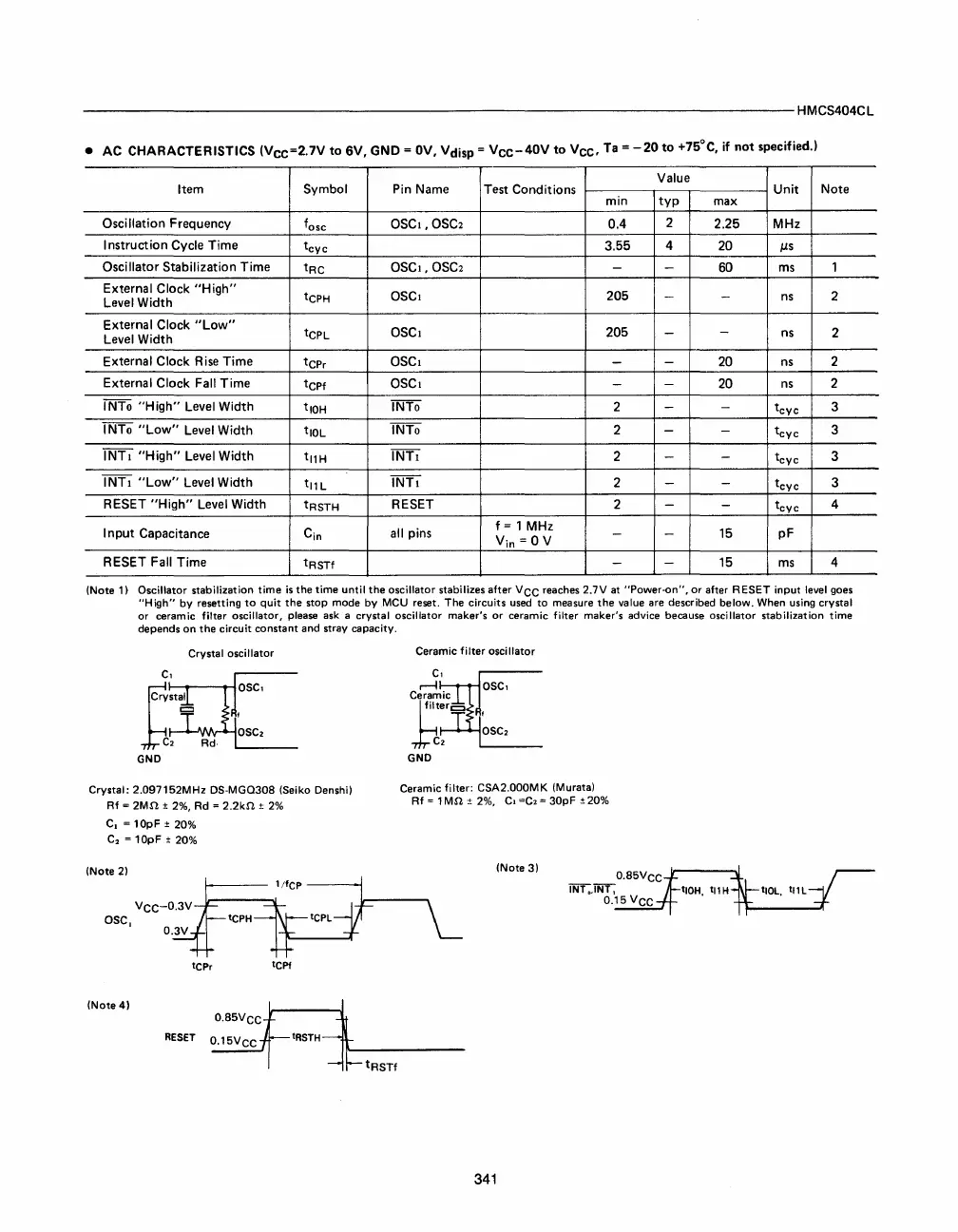
Oscillator stabilization time
is
the time until the oscillator stabilizes after
VCC
reaches 2.7V
at
'"Power-on'", or after RESET input
level
goes
'"High'"
by
resetting
to
quit the stop mode
by
MCU
reset. The circuits
used
to measure the
value
are described below.
When
using
crystal
or ceramic filter oscillator,
please
ask
a crystal oscillator maker's or ceramic filter maker's advice because oscillator stabilization time
depends on the circuit constant and stray capacity.
Crystal oscillator
GND
Crystal: 2.097l52MHz
DS-MGQ308
(Seiko
Denshi)
Rf
=
2Mn
±
2%,
Rd
=
2.2kn
±
2%
C,
= 10pF ±
20%
C
2
= 10pF ±
20%
(Note
2)
VCC-O.3V
asc,
tCPr
tCPf
(Note
4)
RESET
Ceramic filter oscillator
Ceramic filter:
CSA2.000MK
(Murata)
Rf
= 1 Mn ±
2%,
C,
=C.
= 30pF
±20%
(Note
3)
341



 To Next Page