HMCS404CL--------------------------------------------------------------------------
30
Ta
=
-20
- +75°C
---.
20
«
E
c:
·E
10
o
b
~
If/v
ltv
1-1/
/v
~
V
~v
2
VCC=6V
V
7
V
/
VCC=5V
IY
/
:;11
//
v
VCC=4V
L.:::-r-
v
......
/
1 1
VCC=2.7V
I--
~
[.....---i--"
3 4
5
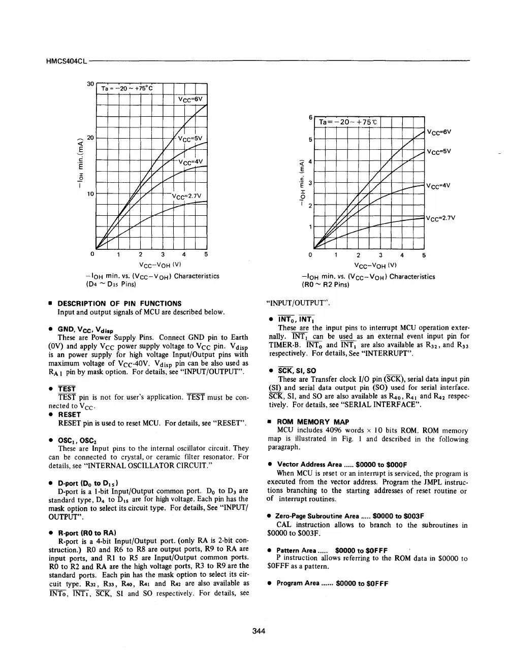
VCC-VOH
(V)
-IOH
min.
vs.
(VCC-VOH)
Characteristics
(D4 ~ DIs
Pins)
• DESCRIPTION OF PIN FUNCTIONS
Input and output
signals
of
MCU
are
described below.
• GND.
Vee.
Vdisp
These
are
Power Supply
Pins.
Connect
GND
pin to Earth
(OV)
and
apply
Vee
power supply voltage to
Vee
pin. V
disp
is
an power supply for
high
voltage Input/Output pins with
maximum voltage
of
Vcc-40V.
Vdisp
pin
can
be
also
used
as
RA
1
pin
by mask option. For details,
see
"INPUT/OUTPUT".
• TEST
TEST
pin
is
not for user's application. TEST must
be
con-
nected to
Vee.
• RESET
RESET pin
is
used to reset
MCU.
For details,
see
"RESET".
•
OSC
I
.OSC
2
These
are
Input pins to the internal oscillator circuit. They
can
be
connected to crystal, or ceramic filter resonator. For
details,
see
"INTERNAL OSCILLATOR CIRCUIT."
• D-port
(Do
to
0
15
)
D-port
is
a I-bit Input/Output common port.
Do
to
D3
are
standard type,
D4
to
DIS
are
for
high
voltage. Each pin
has
the
mask option to select its circuit type. For details,
See
"INPUT/
OUTPUT".
• R-port
(RO
to
RA)
R-port
is
a 4-bit Input/Output port. (only
RA
is
2-bit con-
struction.)
RO
and R6 to
R8
are output ports, R9 to
RA
are
input ports, and RI to
RS
are
Input/Output common ports.
RO
to
R2
and
RA
are the high voltage ports,
R3
to R9 are the
standard ports. Each pin
has
the mask option to select its
cir-
cuit type.
R32,
R33,
R40,
R41
and
R42
are
also
available
as
INTo, INTI,
SCK,
SI
and
SO
respectively. For details,
see
344
6
5
c:
·E
3
:x:
o
"I
2
o
Ta=-20-
+75"C
V
V
V
/v
'/
V
f7
V
-
l----
/ V
/V
/t:0
V
/~
I--
l-
I--
~
.....
v
I.---
lot
V
2
3
4
VCC-VOH
(V)
1/
VCC=6V
V
VCC=5V
f--
VCC=4V
+--
VCC=2.7V
5
-IOH
min.
vs.
(V
CC-
VOH)
Characteristics
(RO
~
R2
Pins)
"INPUT/OUTPUT" .
•
INTo.
INTI
These
are
the input pins to interrupt
MCU
operation exter-
nally.
INTI
can
be
used
as
an
external event input pin for
TIMER-B.
INTo
and
INTI
are
also
available
as
R
32
, and
R33
respectively. For details,
See
"INTERRUPT".
• SCK, SI.
SO
These
are
Transfer clock I/O pin (SCK), serial data input pin
(SI) and serial data output
pin
(SO) used for serial interface.
SCK,
SI, and
SO
are
also
available
as
~o,
R41
and
~2
respec-
tively. For details,
see
"SERIAL INTERFACE".
• ROM MEMORY MAP
MCU
includes 4096 words x 10 bits
ROM.
ROM
memory
map
is
illustrated
in
Fig.
I and described
in
the following
paragraph.
• Vector Address Area ..... $0000
to
$OOOF
When
MCU
is
reset or
an
interrupt
is
serviced, the program
is
executed from the vector address. Program the
JMPL
instruc-
tions branching to the starting addresses
of
reset routine or
of
interrupt routines.
•
Zero-Page
Subroutine Area ..... $0000
to
$003F
CAL
instruction allows to branch to the subroutines
in
$0000
to
$003F.
• Pattern Area ..... $0000
to
$OFFF
P instruction allows referring
to
the
ROM
data
in
$0000 to
$OFFF
as
a pattern.
• Program Area ...... $0000
to
$OFFF


 To Next Page
 Loading...



