------------------------------------------------------------------------HMCS404CL
• SERIAL INTERFACE
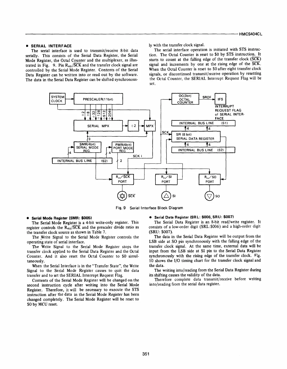
The serial interface
is
used to transmit/receive 8-bit data
serially. This consists
of
the Serial Data Register, the Serial
Mode Register, the Octal Counter and the multiplexer,
as
illus-
trated in Fig. 9. Pin R
4o
/SCK and the transfer clock signal are
controlled by the Serial Mode Register. Contents
of
the Serial
Data Register can be written into
or
read
out
by the software.
The data in the Serial Data Register can be shifted synchronous-
ly with the transfer clock signal.
The serial interface operation
is
initiated with STS instruc-
tion. The Octal Counter
is
reset
to
$0
by
STS instruction.
It
starts
to
count at the falling edge
of
the transfer clock (SCK)
signal and increments by one at the rising edge
of
the SCK.
When the Octal Counter
is
reset to $0 after eight transfer clock
signals,
or
discontinued transmit/receive operation
by
resetting
the Octal Counter, the SERIAL Interrupt Request Flag will
be
set.
INTERRUPT
REQUEST FLAG
of
SERIAL INTER-
FACE
Fig.9
Serial Interface Block Diagram
• Serial Mode Register (SMR:
$005)
The Serial Mode Register
is
a 4-bit write-only register. This
register controls the
~o/SCK
and the prescaler divide ratio
as
the transfer clock source
as
shown in Table 7.
The
~rite
Signal to the Serial Mode Register controls the
operating state
of
serial interface.
The Write Signal
to
the Serial Mode Register stops the
transfer clock applied
to
the Serial Data Register and the Octal
Counter. And it also reset the Octal Counter
to
$0 simul-
taneously.
When the Serial Interface
is
in the "Transfer State", the Write
Signal
to
the Serial Mode Register causes
to
quit the data
transfer and
to
set the SERIAL Interrupt Request Flag.
Contents
of
the Serial Mode Register will be changed
on
the
second instruction cycle after writing into the Serial Mode
Register. Therefore,
it
will be necessary
to
execute the STS
instruction after the data in
the
Serial Mode Register has been
changed completely. The Serial Mode Register will be reset
to
$0
by
MCU
reset.
351
• Serial Data Register (SRL: $006. SRU: $007)
The Serial Data Register
is
an 8-bit read/write register.
It
consists
of
a low-order digit (SRL:$006) and a high-order digit
(SRU: $007).
The data in the Serial Data Register will be
output
from the
LSB side at SO pin synchronously with the falling edge
of
the
transfer clock signal. At the same time, external data will be
input from the
LSB
side at SI pin to the Serial Data Register
synchronously with the rising edge
of
the transfer clock. Fig.
10 shows the I/O timing chart for the transfer clock signal and
the data.
The writing into/reading from the Serial Data Register during
its shifting causes the validity
of
the data.
Therefore complete data transmit/receive before writing
into/reading from the serial data register.


 To Next Page
 Loading...



