HMCS404CL--------------------------------------------------------------------------
Table 15. TIMER-B Interrupt Request
Flag
TIMER-B
Interrupt
Request Flag
o
I nterrupt Request
No
Yes
Table 16. TIMER-B Interrupt
Mask
TIMER-B Interrupt
Mask
o
• INPUT/OUTPUT
Interrupt
Request
Enable
Disable
(Mask)
The
MCV
provides
58
Input/Output
pins, and
they
are con-
sist
of
32 standard pins and 26 high voltage pins. Each standard
pin may have one
of
three mask options: (A) "Without pull-
up
MOS
(NMOS open drain)", (B) "With pull-up MOS",
or
(C) "CMOS". And also each high voltage pin may have one
of
two mask options: (D) "Without pull-down
MOS
(PMOS
Pull
up
MOS
(e)
approximately
40kn
to
160kn
(Vee
= 5V)
approximately
75kn
to
1
Mn
(Vee
= 3V)
Vee
Vee
PMOS(B)
approximately
5kn
NMOS(A)
approximately
1
kn
open
drain)",
or
(E)
"With pull-down MOS". As pull-down
MOS
is
connected
to
internal V disp line, select
RAI
/V
d~
pin
as
V disp
with
mask
option
when
at
least
one
high voltage pin
is
selected as "With pull-down MOS"
option.
When any
Input/Output
common
pin is used as
input
pin,
it
is
necessary
to
select the mask
option
and
output
data as shown
in Table 18.
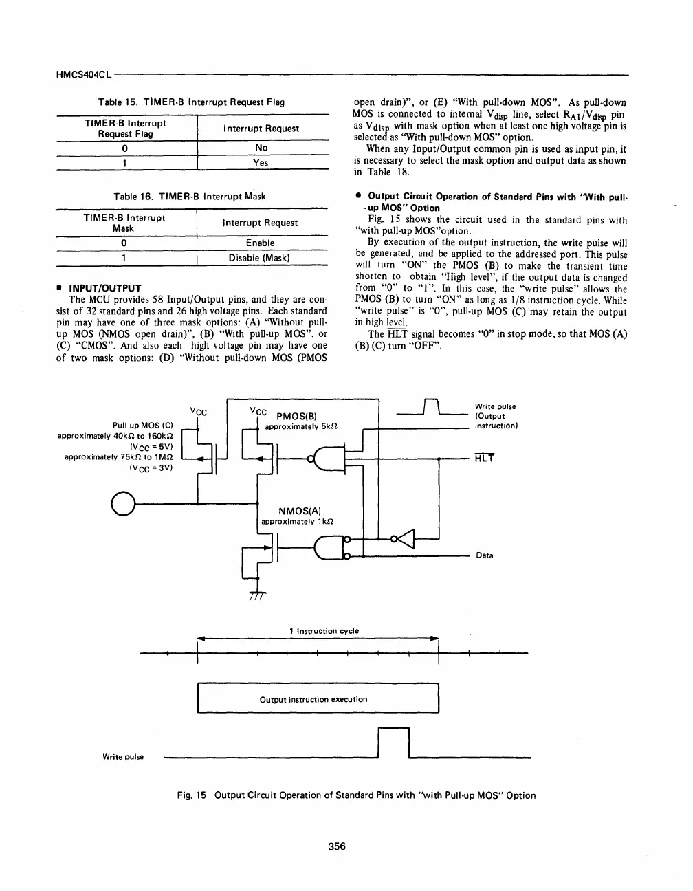
•
Output
Circuit Operation
of
Standard Pins with ''With pu"-
- up MOS" Option
Fig. 15 shows the circuit used in
the
standard pins with
"with
pull-up MOS"option.
By execution
of
the
output
instruction,
the
write pulse will
be generated, and be applied
to
the addressed
port.
This pulse
will turn
"ON"
the PMOS (B) to make the transient time
shorten to obtain
"High level",
if
the
output
data
is changed
from
"0"
to
"I".
In
this case, the
"write
pulse"
allows the
PMOS (B) to turn
"ON"
as long
as
I
/8
instruction cycle. While
"write
pulse"
is
"0",
pull-up
MOS
(C)
may
retain the
output
in
high level.
The HLT signal becomes
"0"
in
stop
mode,
so
that
MOS
(A)
(B) (C)
turn
"OFF".
Write pulse
(Output
instruction)
~--~------~----
HlT
Data
1
Instruction
cycle
Output
instruction
execution
Write
pulse
___
-----'nL...--
__
Fig.
15
Output Circuit Operation
of
Standard
Pins
with
"with
Pull-Up MOS" Option
356


 To Next Page
 Loading...



