--------------------------------------------------------------------------HMCS404CL
• D-pc)ft
D-port
is
I-bit I/O port, and it has
16
Input/Output
common
pins. It can be set/reset by the
SED/RED and SEDD/REDD
instructions, and can
be
tested
by
the TD and TDD instructions.
Table
17 shows
the
classification
of
standard pins, high voltage
pins and the
Input/Output
pins circuit types.
• R-port
R-port
is
4-bit I/O port.
It
provides 20
input/output
com-
mon
pins, 16 output-only pins, and 6 input-only pins. Data
input
is
processed using the LAR and LBR instructions and data
output
is
processed using the LRA and LRB instructions. The
MCV
will
not
be affected by writing into
the
input-only and/or
non-existing ports, invalid data will be read
by
reading from the
output-only
and/or
non-existing ports .
The
R32,
R33, R40,
R41
and
R42
pins are also used
as
the INTo.
INTI,
SCK,
SI
and
SO
pins respectively. Table
17
shows the
classification
of
standard pins, high voltage pins and
Input/
Output pins circuit types.
• RESET
The
MCV
is
reset by setting RESET pin to
"1".
At power
ON
or recovering from stop mode, apply RESET input more
than
tRC
to
obtain the necessary time for oscillator stabiliza-
tion. In
other
cases,
the
MCV
reset requires
at
least
two
instruc-
tions cycle time
of
RESET input.
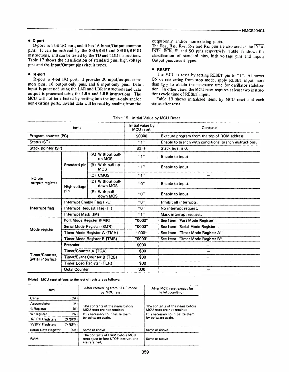
Table
19
shows initialized items by
MCV
reset and each
status after reset.
Table 19 Initial Value by MCU
Reset
Items
I
nitial value by
Contents
MCU
reset
Program counter
(PC)
$0000
Execute program from the
top
of
ROM
address.
Status (ST)
"1"
Enable
to
branch
with
conditional branch instructions.
Stack pointer
(SP)
$3FF Stack level
is
O.
(A)
Without
pull-
"1"
Enable
to
input.
upMOS
Standard pin
(B)
With pull-up
"1"
Enable
to
input
MOS
(C)
CMOS
"1"
-
I/O
pin
(0)
Without
pull-
output
register
"0"
Enable
to
input.
High voltage
down
MOS
pin
(E)
With
pull-
"a"
Enable
to
input.
down
MOS
Interrupt Enable Flag
(I/E)
"0"
I
nhibit
all interrupts.
Interrupt
flag
Interrupt Request Flag
(I
F)
"0"
No interrupt request.
Interrupt Mask
(1M)
"1"
Mask
interrupt
request.
Port Mode Register
(PM
R)
"0000"
See
Item
"Port
Mode Register".
Serial Mode Register (SMR)
"0000"
See
Item "Serial Mode Register".
Mode register
Timer Mode Register A (TMA)
"000"
See
Item
"Timer
Mode Register
A".
Timer Mode Register B (TMB)
"0000"
See
Item
"Timer
Mode Register
B".
Prescaler
$000
-
Timer/Counter A (TCA)
$00
-
Timer/Counter,
Timer/Event Counter B (TCB)
$00
-
Serial interface
Timer Load Register (TLR)
$00
-
Octal Counter
"000"
-
(Note) MCU reset affects
to
the
rest
of
registers as follows:
Item
After recovering from STOP mode
After
MCU
reset
except
for
by
MCU
reset
the
left
condition
Carry
(CA)
Accumulator
(A)
The
contents
of
the
items before The
contents
of
the
items before
8 Register
(8)
MCU
reset are
not
retained.
MCU
reset are
not
retained.
W Register
(W)
It
is
necessary
to
intialize
them
It
is
necessary
to
initialize
them
X!SPX Registers (X/SPX)
by software again. by software again.
Y /SPY Registers
(Y/SPY)
Serial
Data Register
(SR)
Same
as
above
Same
as
above
The
contents
of
RAM before
MCU
RAM
reset (just before STOP instruction)
Same
as
above
are retained.
359


 To Next Page
 Loading...



