--------------------------------------------------------HMCS44C,HMCS44CI
ecution
of
input instruction.
The
Do
to
D3
terminals are
also
addressed directly
by
the
op-
erand n
of
input/output instruction and can
be
set or reset.
The block diagram
is
shown
in
Figure
14
and the
110
timing
is
shown
in
Figure
15.
SED.
RED.SEDD. [
REDO
Instruction
TO
(
Instruction
One
Instruction Cycle
~
-
On
Set/Reset
Instruction
n
lSI
Din
X
Set Signal by the reset function
Set Instruction
Reset
Instruction
___
-t
On
latch
Figure
14
1-bit Discrete
I/O
Block Diagram
On
Test
~
Instruction
.n...
r--
On
Sam lin
p g
Clock
Figure
15
1-bit Discrete
I/O
Timing
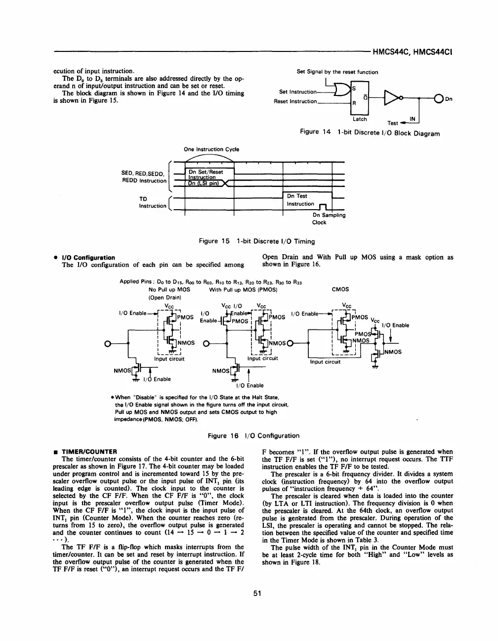
• I/O Configuration
The
110
configuration
of
each
pin
can
be
specified among
Open Drain and With Pull
up
MOS
using a mask option as
shown
in
Figure
16.
Applied Pins;
Do
to
0,5.
Roo
to
R03.
R,o
to
R,3.
R20
to
R23.
R30
to
R33
No
Pull
up
MOS
With
Pull
up MOS (PMOS)
CMOS
(Open
Drain)
Vcc
I/O
Enable--f--~'
S
I PMO
I i
I
I I
I I
: NMOS
I I
L
____
J
Input circuit
I-r
I/~
Enable
* When "Disable" is specified
for
the
I/O
State at the Halt State.
the
I/O
Enable signal shown in the figure turns
off
the input circuit.
Pull
up
MOS and NMOS output and sets CMOS output
to
high
impedance
(PMOS. NMOS;
OFF).
Figure
16
I/O
Configuration
• TIMER/COUNTER
The timer/counter consists of the 4-bit counter and the 6-bit
prescaler as shown
in
Figure
17.
The 4-bit counter may
be
loaded
under program control and
is
incremented toward
15
by
the pre-
scaler overflow output pulse or the input pulse
of
INTI
pin
(its
leading edge
is
counted). The
clock
input to the counter
is
selected
by
the CF F/F. When the CF F/F
is
"0",
the
clock
input
is
the prescaler overflow output pulse (Timer Mode).
When the CF
F/F
is
"I",
the
clock
input
is
the input pulse
of
INTI
pin
(Counter Mode). When the counter reaches zero (re-
turns from
15
to zero), the overflow output pulse
is
generated
and the counter continues to count
(14
-
15
- 0 - 1 - 2
·
..
).
The TF
F/F
is
a
flip-flop
which masks interrupts
from
the
timer/counter.
It
can be set and reset
by
interrupt instruction. If
the overflow output pulse
of
the counter
is
generated when the
TF
F/F
is
reset
("0"),
an interrupt request occurs and the TF
F/
51
F becomes
"1".
If
the overflow output pulse
is
generated when
the TF
F/F
is
set
("I
"),
no interrupt request occurs. The TTF
instruction enables the TF F
/F
to
be
tested.
The prescaler
is
a 6-bit frequency divider.
It
divides a system
clock
(instruction frequency)
by
64
into
the overflow output
pulses
of
"instruction frequency + 64".
The prescaler
is
cleared when data
is
loaded into the counter
(by
L T A or L TI instruction). The frequency division
is
0 when
the prescaler
is
cleared. At the 64th
clock,
an overflow output
pulse
is
genl:rated from the prescaler. During operation
of
the
LSI, the prescaler
is
operating and cannot be stopped. The rela-
tion between the specified value
of
the counter and specified time
in
the Timer Mode
is
shown
in
Table
3.
The pulse width
of
the
INTI
pin
in
the Counter Mode must
be
at least
2-cycle
time
for
both "High" and
"Low"
levels as
shown
in
Figure
18.
 Loading...

