HMCS45C,HMCS45CL--------------------------------------------------------
The accumulator and the lower 2 bits
of
B register are as-
signed into the address part
of
the program counter.
The
upper 2
bits of B register, Carry
FIF, and the operand
PI,
po
are ORed
with the page part
of
the program counter.
TBR
instruction
is
executed regardless
of
the Status FIF, and
does not affect the Status F/F.
• SUBROUTINE
JUMP
There are two types
of
subroutine jumps. They are explained
in the following paragraphs.
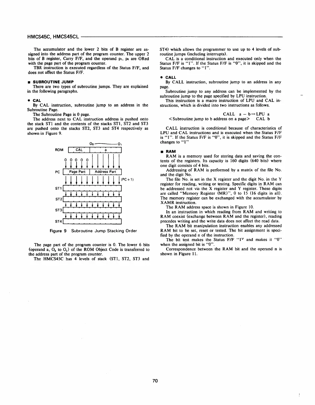
• CAL
By
CAL instruction, subroutine jump to an address
in
the
Subroutine Page.
The Subroutine Page
is
0 page.
The address next to CAL instruction address
is
pushed onto
the stack ST! and the contents
of
the stacks ST!,
ST2
and
ST3
are pushed onto the stacks ST2,
ST3
and ST4 respectively as
shown in Figure
9.
06----01
ROM
I : :
~
: : I
111111
PC
I pape
~ar~
I Address Part
l l l ! l l l l l l l
(PC
+
1)
STll
: : : : : : : : : :
t t t t t t
tit
t t
ST21
: : : : : : : : : :
ttttttttttt
ST3I:
::::::::
tttttttttti
S
T4
1 : : : : : : : : : :
Figure 9 Subroutine
Jump
Stacking
Order
The page part
of
the program counter
is
O.
The lower 6 bits
(operand a, 0
6
to 0
1
)
of
the ROM Object Code
is
transferred to
the address part
of
the program counter.
The HMCS45C has 4 levels
of
stack (ST!, ST2,
ST3
and
70
ST4) which allows the programmer to use up to 4 levels
of
sub-
routine jumps (including interrupts).
CAL
is
a conditional instruction and executed only when the
Status F
IF
is
"1".
If
the Status F
IF
is
"0",
it
is
skipped and the
Status F/F changes to
"I".
• CALL
By
CALL instruction, subroutine
jump
to an address
in
any
page.
Subroutine
jump
to any address can be implemented
by
the
subroutine jump to the page specified
by
LPU instruction.
This instruction
is
a macro instruction
of
LPU and CAL in-
structions, which
is
divided into two instructions as follows.
CALL a -
b--
LPU a
< Subroutine jump
to
b address on a page> CAL b
CALL instruction
is
conditional because
of
characteristics
of
LPU and CAL instructions and
is
executed when the Status F/F
is
"I".
If
the Status F/F
is
"0",
it
is
skipped and the Status F/F
changes to
"1"
•
RAM
RAM
is
a memory used for storing data and saving the con-
tents
of
the registers. Its capacity
is
160 digits (640 bits) where
one digit consists
of
4 bits.
Addressing
of
RAM
is
performed
by
a matrix
of
the
file
No.
and the digit No.
The
file
No.
is
set
in
the X register and the digit No.
in
the Y
register for reading, writing or testing. Specific digits
in
RAM can
be addressed not
via
the X register and Y register. These digits
are called
"Memory Register
(MR)",
0 to
15
(16 digits
in
all).
The memory register can be exchanged with the accumulator
by
XAMR instruction.
The RAM address space
is
shown
in
Figure
10.
In
an instruction
in
which reading from RAM and writing to
RAM coexist (exchange between RAM and the register), reading
precedes writing and the write data does not affect the read data.
The
RAM bit manipulation instruction enables any addressed
RAM bit to be set, reset or tested. The bit assignment
is
speci-
fied
by
the operand n
of
the instruction.
The
bit test makes the Status F/F
"1"
and makes
it
"0"
when the assigned bit
is
"0".
Correspondence between the RAM bit and the operand n
is
shown
in
Figure
11.
 Loading...

