--------------------------------------------------------HMCS45C,HMCS45CL
""
X
0
....
N
C")
'Ct
In
co
"
:..
....
I
co
in
....
I
N
....
y
~
0
....
N
C")
'Ct
In
co
"
co
0)
i
file No .
15
14
13
12
11
10
15
14
13
12
11
10
In
'Ct
C")
N
....
0
a:
a: a:
a:
a:
a:
::E
::E ::E
::E
::E
::E
9
8 7 6
5
4
3
2 1 0
9
8
7 6
5
4
3
2 1
0
<-
digit
No.
--
0)
co
"
co
In
'Ct
C")
N
a:
0
a:
a:
a:
a: a:
a:
a:
a:
a:
::E
::E
::E
::E
::E
::E
::E
::E ::E
::E
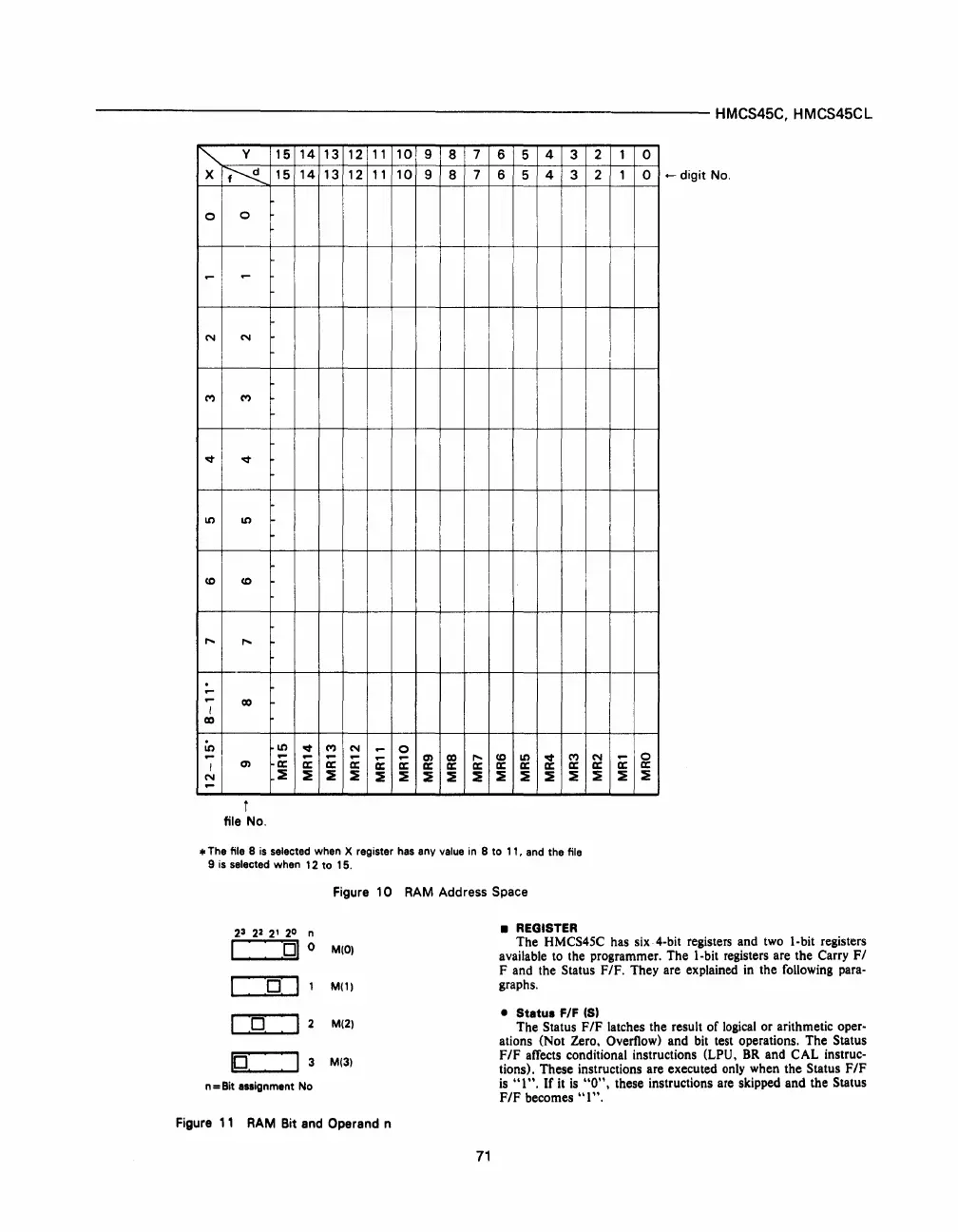
• The file 8
is
selected when X register
has
any
value
in
8 to 11,
and
the file
9
is
selected when 12 to 15.
2
3
22
2'
2
0
n
I
01
0
o
11
o
10:
3
n = Bit assignment No
Figure
10
RAM Address Space
M(O)
M(l)
M(2)
M(3)
•
REGISTER
The HMCS45C has
six4-bit
registers and two I-bit registers
available to the programmer. The I-bit registers are the Carry
FI
F and the Status
F/F.
They are explained
in
the following para-
graphs.
•
Status
F/F (5)
The Status
F/F
latches the result of
logical
or arithmetic oper-
ations (Not Zero. Overflow) and bit test operations, The Status
F/F
affects conditional instructions (LPU.
BR
and CAL instruc-
tions), These instructions are executed
only
when the Status
F/F
is
"t".
If
it
is
"0".
these instructions are skipped and the Status
F/F
becomes
"t",
Figure
11
RAM
Bit and Operand n
71
 Loading...

