HMCS45C,HMCS45CL--------------------------------------------------------
(a)
Configuration
of
Output Pin
Applied Pins;
Reo
to
Re3
No
Pull
up MOS
(Open Drain)
IF
(b)
Configuration
of
I/O
Pin
Applied Pins;
Do
to
0,5,
Roo
to
R03,
R,o
to
R13,
R20
to
R23,
R30
to
R33,
A40
to
R43,
R50
to
R53
No
Pull
up MOS
With
Pull
up
MOS (PMOS)
CMOS
(Open Drain)
Vcc
Vcc
I/O
Enable--r--~'
I PMOS
I i
,..----+1
-+
I
I I
: NMOS
I I
L
____
J
Input circuit
I-a--
I/j
Enable
I/O
Enable-r--~~.
OS
I 0
Vcc
:
~MO
~I/OI
Enable
: NMOS •
1 I
L
___
J NMOS
Input
circuit
.When
"Disable" is specified
for
the
I/O
State at the Halt State,
the
I/O
Enable signal shown in the figure turns
off
the input circuit,
Pull
up MOS and NMOS output and sets CMOS output
to
high
impedance(PMOS, NMOS;
OFF).
Figure
16
I/O
Configuration
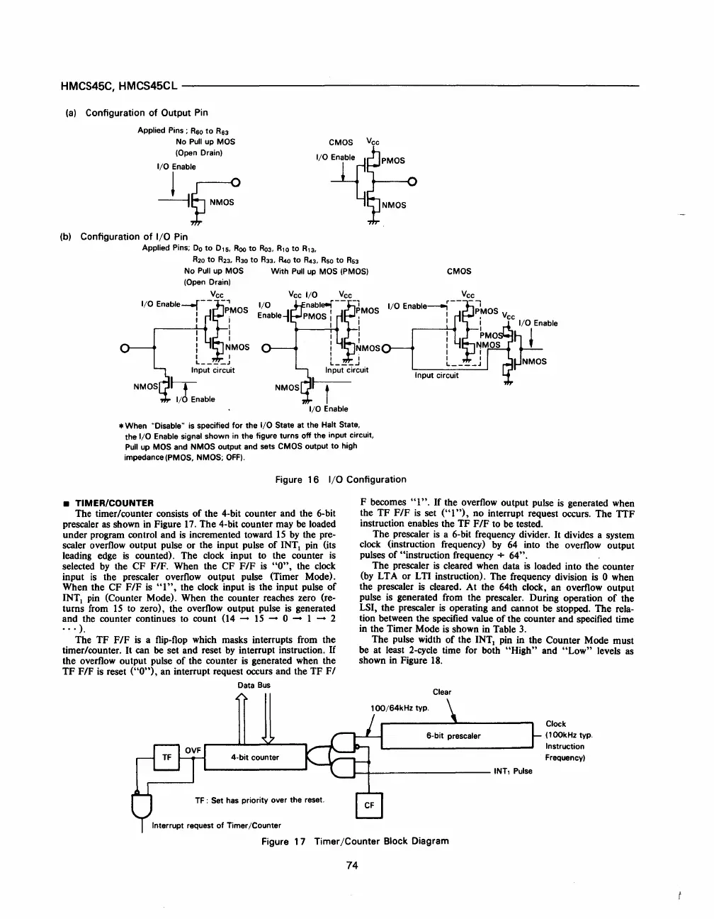
• TIMER/COUNTER
The timer/counter consists
of
the 4-bit counter and the 6-bit
prescaler
as
shown
in
Figure
17.
The 4-bit counter may
be
loaded
under program control and
is
incremented toward
15
by
the pre-
scaler overflow output pulse or the input pulse
of
INTI
pin
(its
leading edge
is
counted). The
clock
input to the counter
is
selected
by
the CF F/F. When the CF F/F
is
"0",
the
clock
input
is
the prescaler overflow output pulse (Timer Mode).
When the CF F/F
is
"1",
the
clock
input
is
the input pulse
of
INTI
pin
(Counter Mode). When the counter reaches zero (re-
turns
from
15
to zero), the overflow output pulse
is
generated
and the counter continues to count
(14
-
15
- 0 - 1 - 2
...
).
The TF
FIF
is
a
flip-flop
which
masks interrupts from the
timer/counter.
It
can be set and reset
by
interrupt instruction.
If
the overflow output pulse
of
the counter
is
generated when the
TF
F/P
is
reset
("0"),
an interrupt request occurs and the TF
F/
Data
Bus
TF: Set has priority over the reset.
Interrupt request
of
Timer/Counter
F becomes
"I".
If
the overflow output pulse
is
generated when
the TF F
IF
is
set
("
1"),
no interrupt request occurs. The
TIF
instruction enables the TF F
IF
to be tested.
The prescaler
is
a 6-bit frequency divider.
It
divides a system
clock
(instruction frequency)
by
64
into the overflow output
pulses
of
"instruction frequency + 64".
The prescaler
is
cleared when data
is
loaded into the counter
(by
LT
A or L
TI
instruction). The frequency division
is
0 when
the prescaler
is
cleared. At the 64th clock, an overflow output
pulse
is
generated from the prescaler. During operation
of
the
LSI, the prescaler
is
operating and cannot
be
stopped. The rela-
tion between the specified value
of
the counter and specified time
in the Timer Mode
is
shown
in
Table
3.
The pulse width
of
the
INTI
pin
in the Counter Mode must
be at least
2-cycle
time
for
both "High" and
"Low"
levels as
shown in Figure
18.
Clear
.......
+-
__________
INT,
Pulse
Clock
(100kHz
typo
Instruction
Frequency)
Figure 1 7 Timer
/Counter
Block Diagram
74
 Loading...

