STRUCTURE
2.2. REFRIGERANT CYCLE
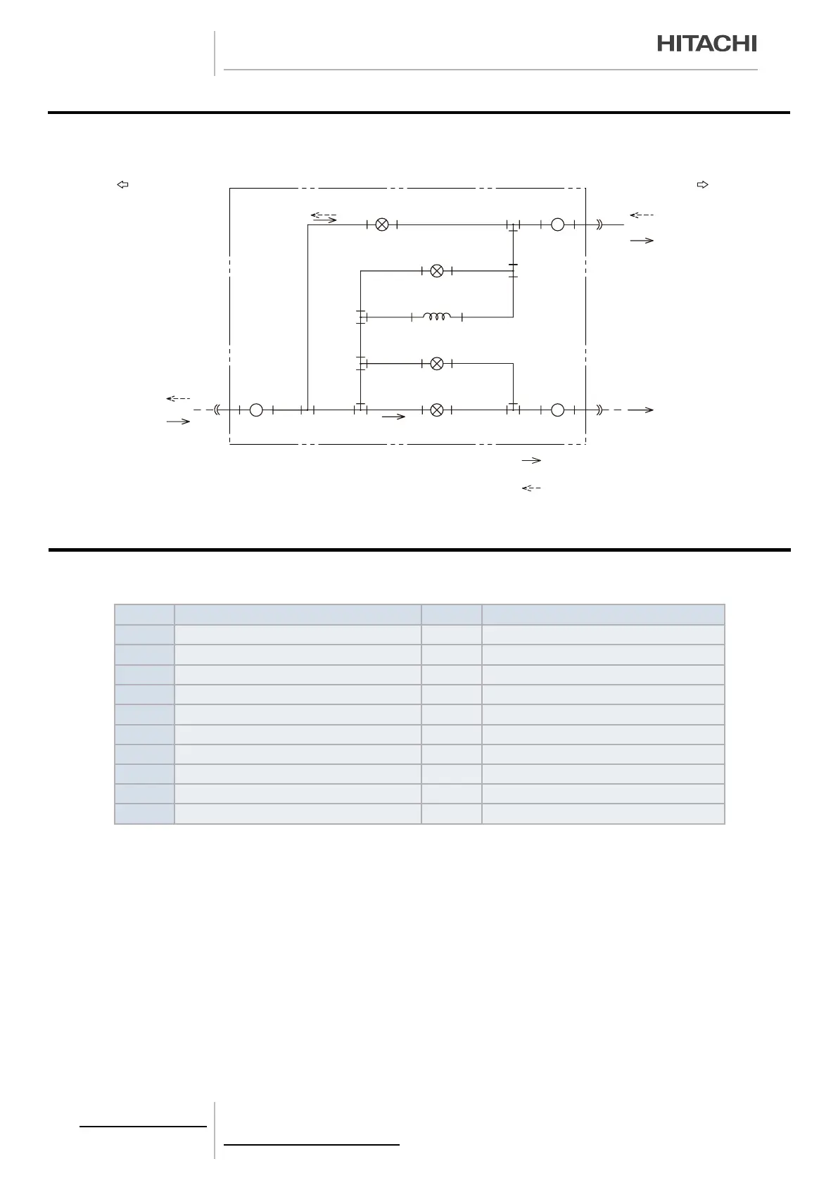
2.2.1. CH UNIT - CH-(6.0/10.0)N2
To Indoor Unit To Outdoor Unit
High Pressure Gas
High Pressure Gas
Strainer
Strainer
Strainer
S
S
S
MVD1
Capillary Tube
MVD1
MVD2
MVS2
MVS1
Electric Expansion Valve
Electric Expansion Valve
Electric Expansion Valve
Electric Expansion Valve
Low Pressure Gas
Low Pressure Gas
Low Pressure Gas
: Refrigerant Flow Direction
(Cooling Operation)
: Refrigerant Flow Direction
(Heating Operation)
2.3.
NECESSARY TOOLS AND INSTRUMENT LIST FOR INSTALLATION
No. Tool No. Tool
1 Handsaw 11 Spanner
2 Phillips Screwdriver 12 Charging Cylinder
3 Vacuum Pump 13 Gauge Manifold
4 Refrigerant Gas Hose 14 Cutter for Wires
5 Megohmmeter 15 Gas Leak Detector
6 Copper Pipe Bender 16 Leveller
7 Manual Water Pump 17 Clamper for Solderless Terminals
8 Pipe Cutter 18 Hoist (for Indoor Unit)
9 Brazing Kit 19 Ammeter
10 Hexagon Wrench 20 Voltage Meter
PMML0309A rev.1 - 09/2015 - P5416573
10

 Loading...


