SAFETY SUMMARY
1. SAFETY SUMMARY
2. STRUCTURE
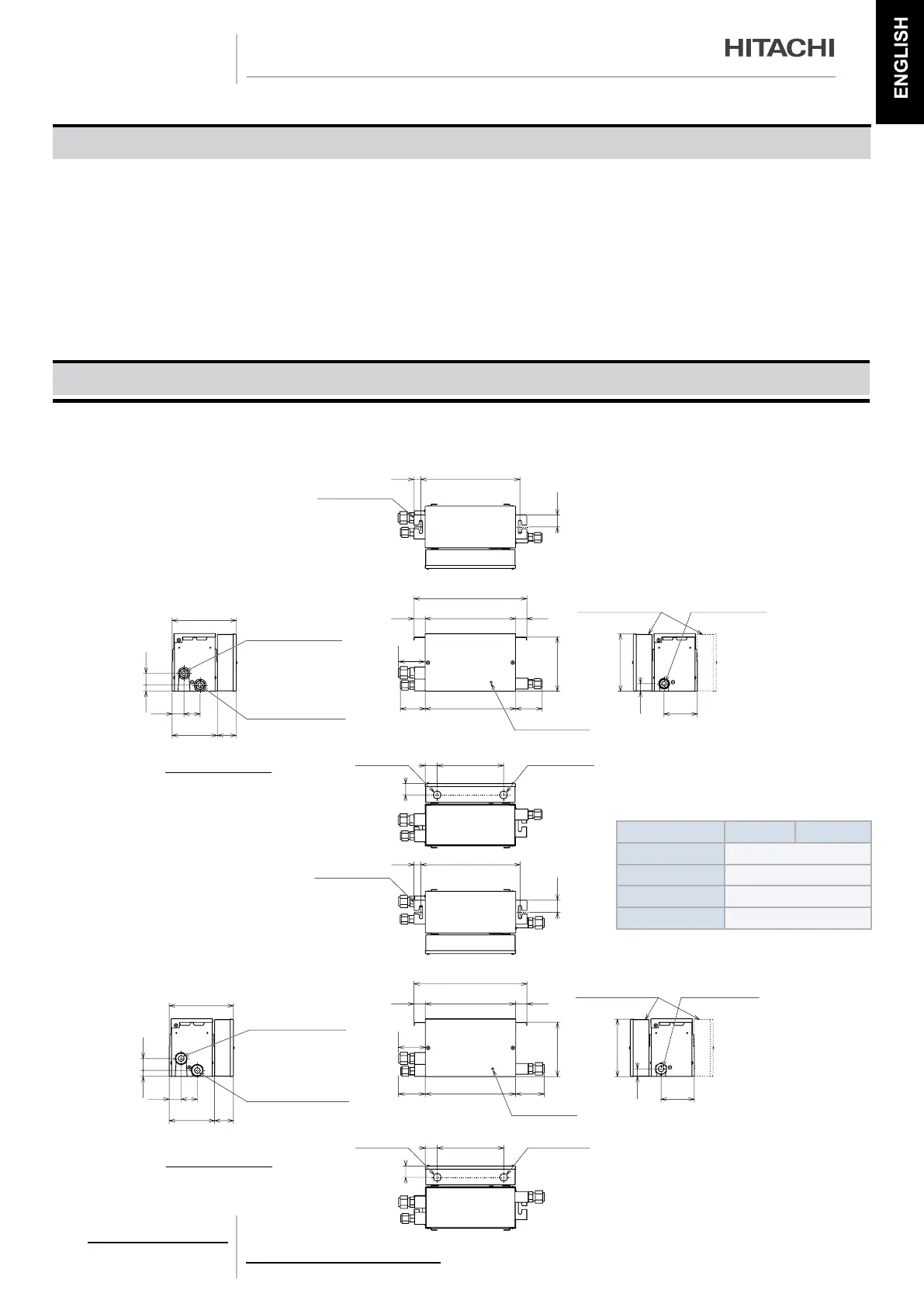
2.1 DIMENSIONS
2.1.1. MODEL: CH UNIT – CH-(6.0/10.0)N2
WARNING:
−− Do not perform installation work, refrigerant piping work and electrical wiring connection without referring to our installation
manual.
−− Check that the ground wire is securely connected.
−− Connect a fuse of specied capacity.
CAUTION:
- Do not install the CH unit and cable within approximately 3 meters from strong electromagnetic wave radiators such as medical
equipment.
CH-6.0N2
Unit: mm
(For Suspension Bolt)
Refrigerant Gas Pipe
Connection (Low Pressure)
Refrigerant Gas Pipe
Connection (High/LowPressure)
Earth Terminal (M5)
Electrical Box
Refrigerant Gas Pipe
Connection
Indoor Unit Connecting Side
(Available for
both sides)
(Ø15.88 Flare Nut)
Hole for
Power Supply Line
(Ø20)
(in Electrical Box)
Hole for
Operating Line
Outdoor Unit Connecting Side
(Ø15.88 Flare Nut)
(Ø19.05Flare Nut)
Suspension Bracket
2-11x34 Slotted Hole
330
376
214
40 54
151 63
301
40 221
30138 38
82 89
111
23
40180
191
25
38
20
39
(Ø20)
Specication:
Model CH-6.0N2 CH-10.0N2
Power Supply AC 1~ 220-240V 50Hz
Refrigerant R410A
Input (W) 20
Net Weight (kg) 7
89
CH-10.0N2
Refrigerant Gas Pipe
Connection (Low Pressure)
Refrigerant Gas Pipe
Connection (High/LowPressure)
Earth Terminal (M5)
Electrical Box
Refrigerant Gas Pipe
Connection
Indoor Unit Connecting Side
(Available for
both sides)
(Ø19.05 Flare Nut)
Hole for
Power Supply Line
(Ø20)
(in Electrical Box)
Hole for
Operating Line
Outdoor Unit Connecting Side
(Ø15.88 Flare Nut)
(Ø19.05Flare Nut)
Suspension Bracket
2-11x34 Slotted Hole
376
214
40 54
151 63
301
40 221
30138 38
82 96
111
180
191
25
20
39
(Ø20)
89
23 330
(For Suspension Bolt)
40
38
PMML0309A rev.1 - 09/2015 - P5416573
9

 Loading...


