This document provides a detailed parts list, disassembly, reassembly, and wiring information for the Hitachi Saber Saw, Model CR 12V.
Function Description
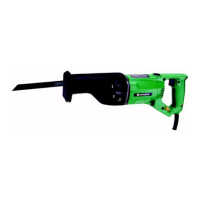
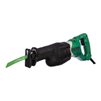
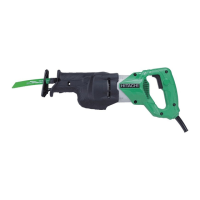
The Hitachi Saber Saw, Model CR 12V, is an electric tool designed for cutting various materials. Its primary function is to provide a reciprocating cutting action, typical of a saber saw, for tasks requiring precision and power. The internal components, including the armature, stator, gears, and plunger, work in conjunction to convert electrical energy into mechanical motion for the saw blade.
Important Technical Specifications
The manual does not explicitly list all technical specifications such as motor power, stroke length, or cutting capacity. However, it provides crucial information regarding fasteners, electrical components, and assembly tolerances.
Fasteners and Torques:
The document specifies various screws and their corresponding tightening torques:
- D4 Tapping Screw: 20 ± 5 kgf-cm (17.4 ± 4.34 in-lb)
- D5 Tapping Screw: 30 ± 5 kgf-cm (26 ± 4.34 in-lb)
- M4 Machine Screw, Flat Hd. Screw: 15 - 20 kgf-cm (13.02 ± 17.4 in-lb)
- M5 Machine Screw: 30 - 55 kgf-cm (26 ± 47.75 in-lb)
- M5 Hexagon Socket Flat Hd. Screw: 50 - 60 kgf-cm (43.41 ± 52.09 in-lb)
- M6 Hexagon Socket Flat Hd. Screw: 80 ± 10 kgf-cm (69.45 ± 8.68 in-lb)
Electrical Specifications (Insulation Tests):
- Insulation Resistance: 7 MΩ or more with a 500V DC Megohm Tester.
- Dielectric Strength:
- AC 4000V/1 minute, with no abnormalities, for 220V - 240V products (and 110V for U.K. products).
- AC 2500V/1 minute, with no abnormalities, for 110V - 127V products (except U.K. products).
Key Components:
The exploded view and parts list detail numerous components, including:
- Plunger (5): The reciprocating element that holds the saw blade.
- Upper Cover Ass'y (11): The upper housing of the tool.
- Gear Cover (26): Encloses the gear mechanism.
- Armature (30): The rotating part of the motor.
- Stator Ass'y: The stationary part of the motor.
- Bearing Cover (29): Covers the bearings.
- Spindle (25): Connects the gear assembly to the plunger.
- Trigger Switch: Controls power to the motor.
- Noise Suppressor: Reduces electrical noise.
- Choke Coil (for N.Z. models): An additional component for noise suppression or power conditioning.
- Carbon Brushes (40): Conduct current to the armature.
- Balance Weight (19): Likely used to reduce vibration during operation.
Usage Features
While the manual focuses on maintenance, the design implies several usage features:
- Blade Mounting: The process of removing the insulation cover and shifting the plunger suggests a specific mechanism for attaching and detaching saw blades (501A).
- Ergonomics: The presence of a Handle Cover (56) indicates a design intended for comfortable gripping and control during operation.
- Power Control: The Trigger Switch allows for user control over the saw's operation.
- Safety: The Insulation Cover (2) and the requirement for specific insulation tests highlight the importance of electrical safety in the tool's design.
Maintenance Features
The manual provides extensive details on disassembly, reassembly, and specific maintenance procedures:
Disassembly and Reassembly Procedures:
The document outlines step-by-step instructions for disassembling and reassembling key components, including:
- Upper Cover Ass'y (11): Removal involves detaching the base, saw blade, insulation cover, and loosening specific screws.
- Plunger (5) from Upper Cover Ass'y (11): Requires removing seal lock screws, which may need heating (100°C - 150°C) for removal due to adhesive.
- Gear Cover (26) from Housing Ass'y (42): Involves removing brush caps, carbon brushes, and tapping screws.
- Armature (30) from Gear Cover (26): Requires removing machine screws.
- Bearing Cover (29) from Armature (30): Involves removing a C-Type Retaining Ring and using a J-173 Puller Attachment (special repair tool, Code No. 970954) with a tubular jig to press the armature out of the bearing cover.
- Gear Ass'y (21) and Spindle (25) from Gear Cover (26): Involves removing a hexagon socket flat head screw (which may require heating due to adhesive), the balance weight, and flat head screws.
Lubrication:
- Grease Application: 30 g of Molub-Alloy #1 grease should be inserted into both the Gear Cover and Upper Cover.
- Specific Lubrication Points: Liberal amounts of grease should be applied to:
- The 6202VVCM Ball Bearing (24) in the Gear Cover (26).
- The Needle Roller (17).
- Connecting Piece (A) (14A).
- The teeth portion of the Gear Ass'y (21).
- The inside of the Connector (14).
- The Connector sliding portion in the Upper Cover Ass'y (11).
- The metal sliding portion of the Plunger (5).
Adhesive Application:
- Seal Lock Screws: Specific screws (M6 x 16 Hexagon Socket Flat Hd. Screws (18), M5 x 12 Hexagon Socket Flat Hd. Screws (15), M5 x 16 Machine Screws (10), M4 x 12 Machine Screws (44), and M4 x 12 Flat Hd. Screws (22)) are seal lock screws. Upon removal, they must be treated with Cemedine 1500 or ThreeBond TB2410 adhesive before reinstallation.
Critical Assembly Steps:
- Bearing Cover (A) (23): Must be assembled when pressure fitting the Gear Ass'y (21) onto the Spindle (25).
- Felt Packing, Packing Washer (6), and 1AP12 O-Ring (8): Must be properly assembled before reinstalling the Plunger (5) into the Upper Cover Ass'y (11).
- Seal Packing (12): Must be assembled when reassembling the Upper Cover Ass'y (11) onto the Gear Cover (26).
- Leadwire Management: Ensure no leadwires are pinched between the Handle Cover (56) and the Housing Ass'y (42) during reassembly.
Insulation Tests:
After any disassembly and repair, insulation resistance and dielectric strength tests are mandatory to ensure electrical safety.
Wiring Diagrams:
The manual includes detailed wiring diagrams (Fig. 6-9) and internal wire arrangements (Fig. 10-17) for different regions (European countries, N.Z., Australia, and other countries), highlighting variations in components like the presence of a Choke Coil. This is crucial for correct electrical maintenance and troubleshooting.